Photo gallery of 2014 synthesizer projects
Thu 26 Jun 2014 by mskala Tags used: music, hardwareHere's a photo gallery (salvaged from my old gallery software in August 2020) of the work I did in 2020 refinishing the end cheeks of a Pittsburgh Modular Cell case and constructing a "universal host" Eurorack module based on an ODROID single-board computer.

LK204-7T-1U USB-LCD module
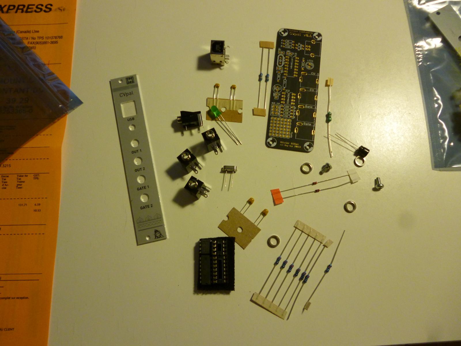
Mutable Instruments CVpal kit
ready to assemble one of the CVpals
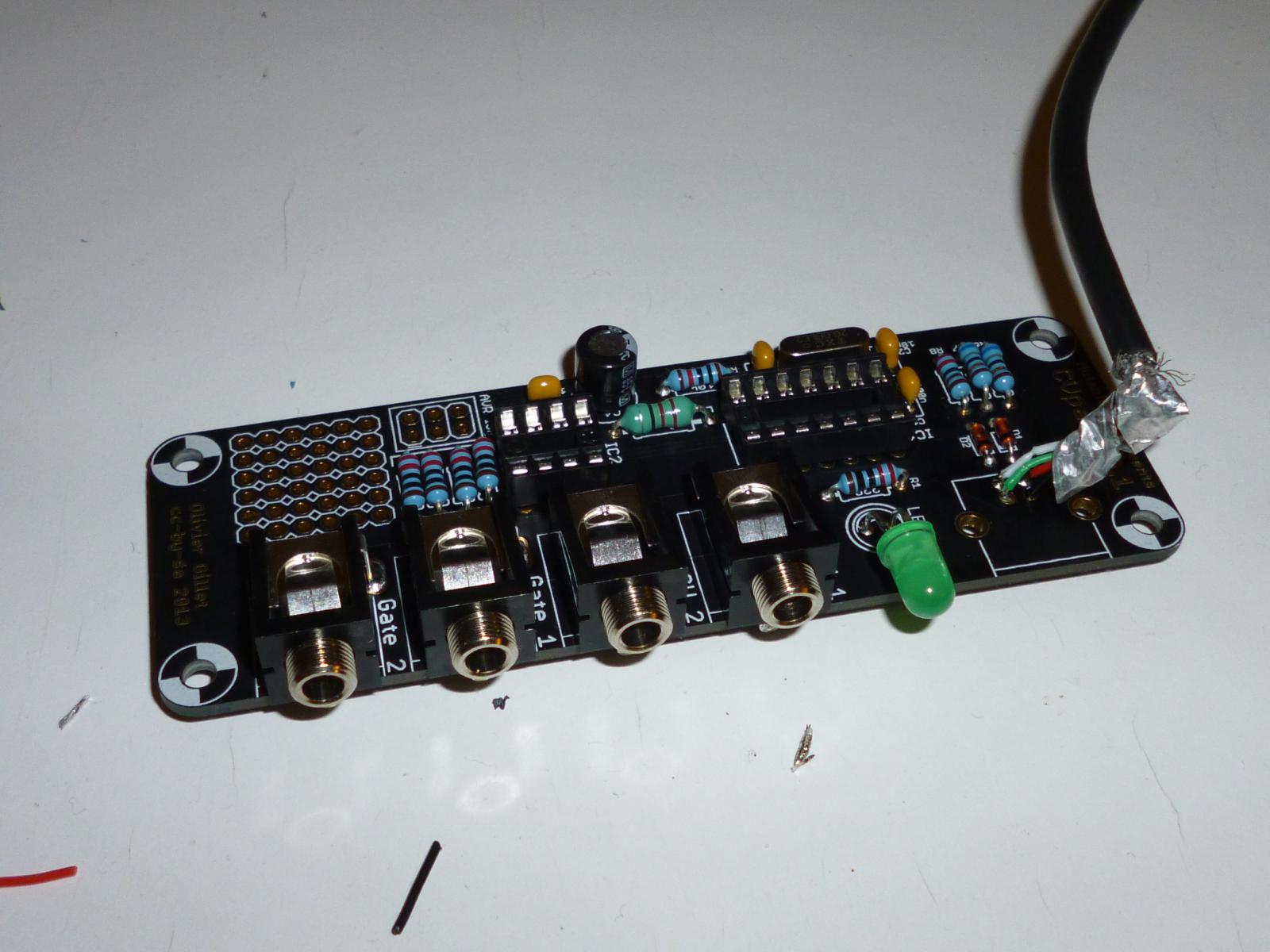
assembled CVpal
Note the modification - I added a captive USB cable, to wire into the ODROID behind the panel, instead of using the socket that came with the kit.
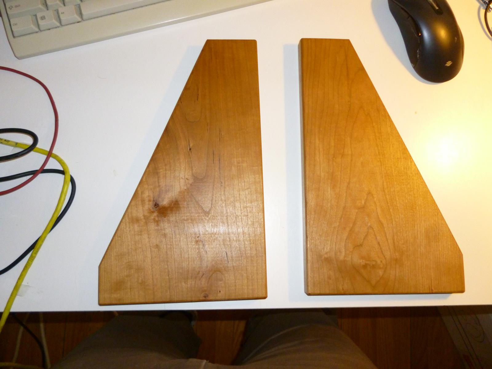
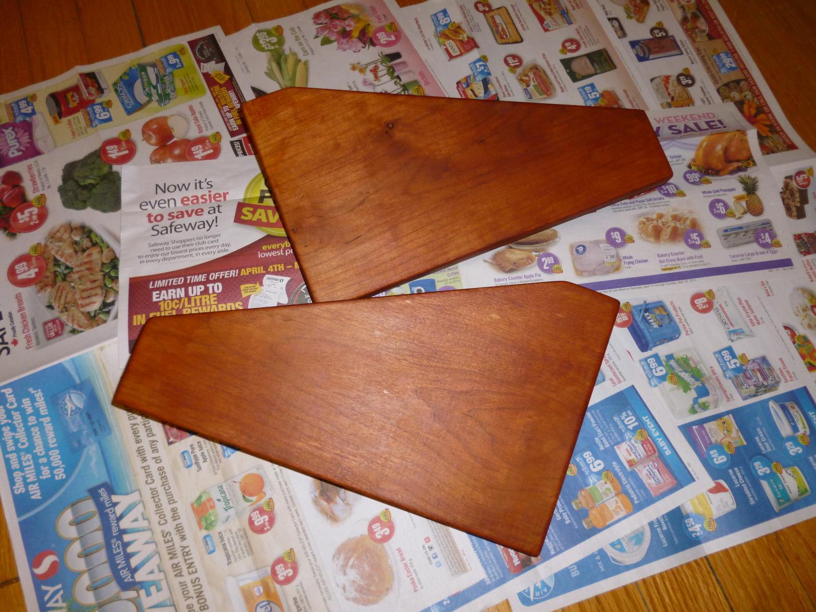
Pittsburgh Modular two-row Cell cheeks
I wasn't happy with the colour and finish on these. The pictures on the Pittsburgh Web site are accurate, so I can't fault the manufacturers; but once I saw the cheeks in person up close, I decided I really wanted them to be darker and glossier. They are supposed to be genuine cherry, and from what I've read, they will darken over time with UV exposure and that process can be hastened by exposing them to direct sunlight. I tried that for a couple days, but how much sun do you think we get in Winnipeg in winter? It also wouldn't address the finish issue.
So the next several images are from my do-it-yourself refinishing...
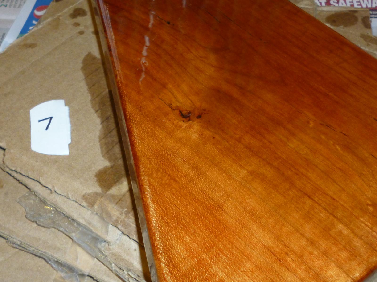
after two coats of rub-on stain

after about three coats of varnish
after seven coats of varnish
Note how the depth of the grain is starting to become visible. The camera doesn't show the very nice shifting iridescence when the angle of light changes.

after ten coats of varnish
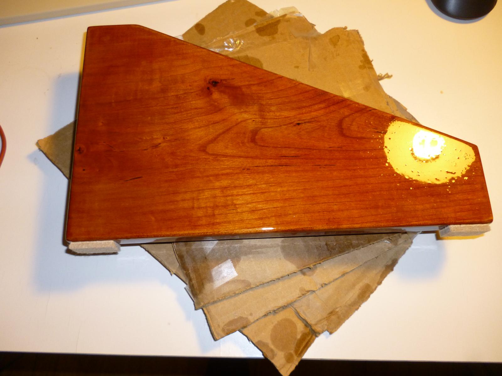
As can be seen in the reflection from the desk lamp, it's not perfect. There is some dust, bubbles, and maybe even some sanding grit caught up in the finish. But it still looks much nicer than it was, and it feels really good to touch.
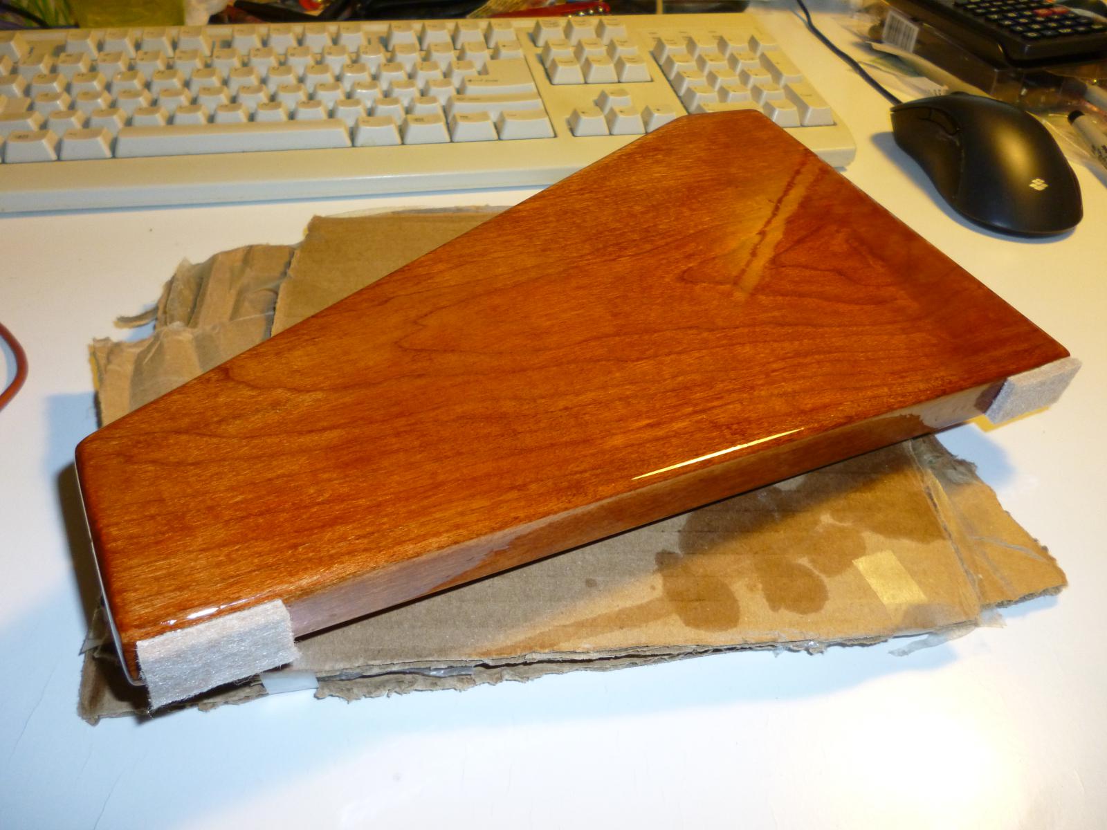
glamour shot
Here the angle is just right to hide the defects and it looks amazing.
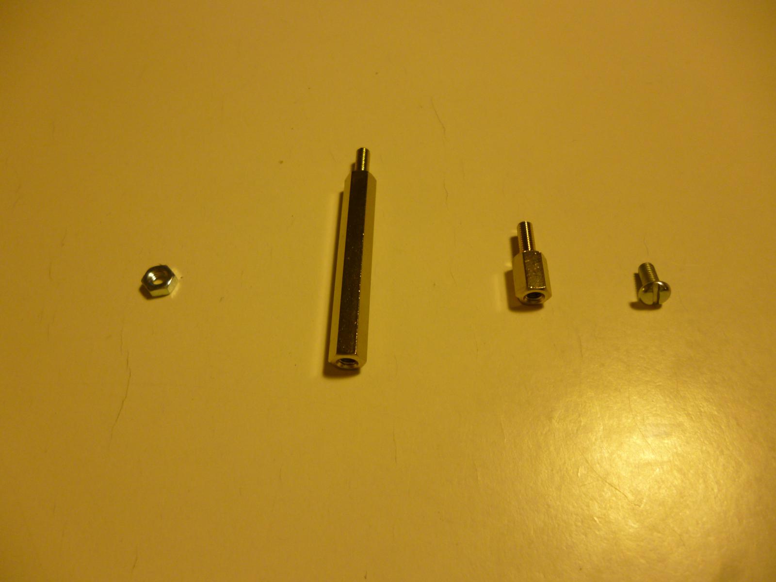
screw puzzle
Hardware for mounting the different circuit boards of the MSK 001 to its front panel. Three male threads and three female in the picture, all supposedly standard M3. All pairings will mate properly, except that the nut will not fit on the long standoff. And this was a common pattern among all the individual pieces of hardware of these types - none of the nuts would fit on any of the long standoffs, and all other pairings worked.
I thought I might have to return the standoffs to the distributor, which would suck because I'd already waited weeks for them on backorder.
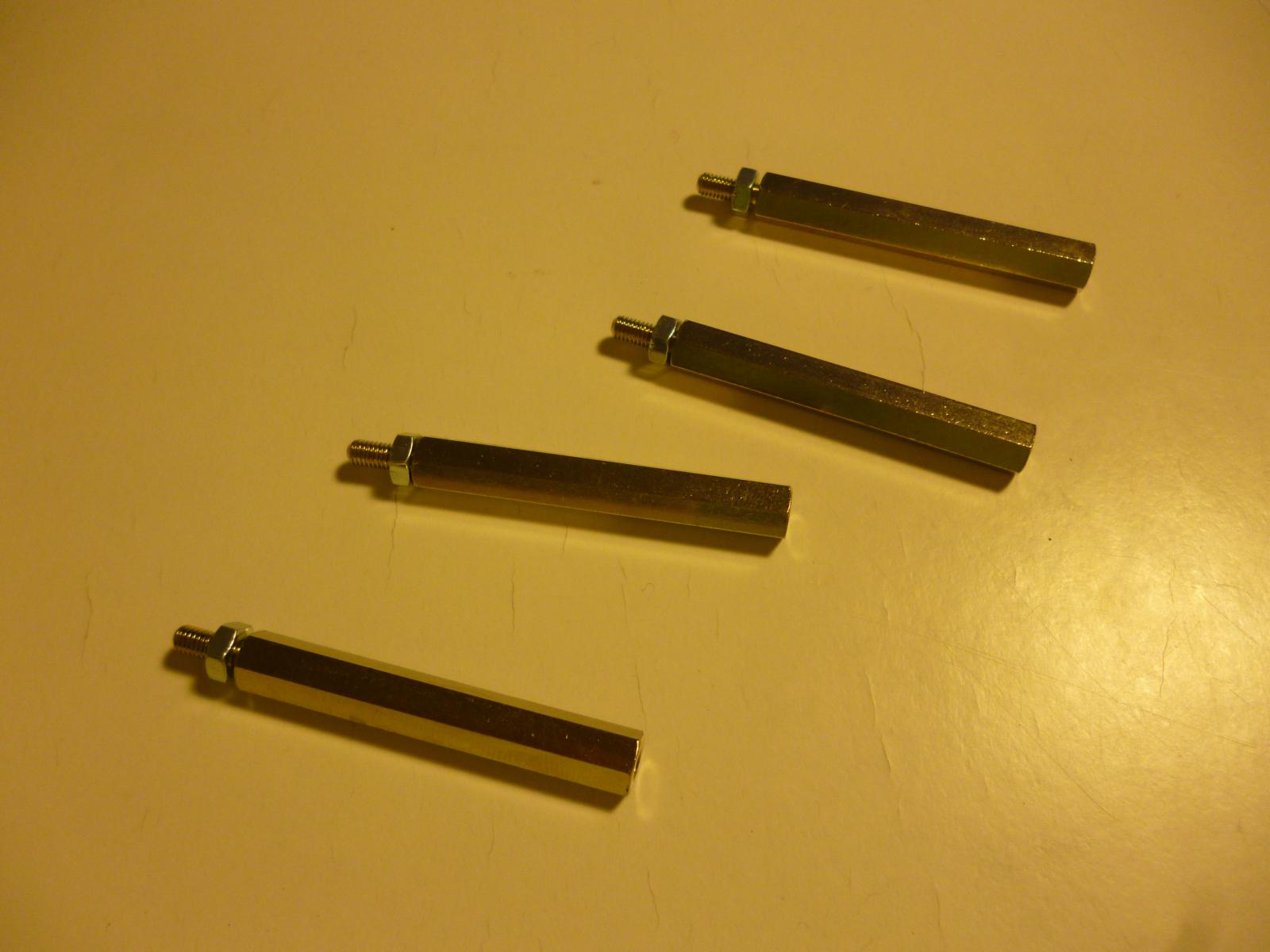
puzzle solved
Figuring there was nothing to lose, I tried just forcing it. And that worked. After screwing a pair together the first time with a lot of difficulty, subsequent attempts with the same pair were reasonably easy. I imagine that the nuts were at the lower limit of their tolerance range for the inner diameter, and the standoff male threads were at their upper limit for outer diameter. If all the other threads (on other types of parts) were near the middle of their ranges, then those pairings would work while this one was difficult. And forcing it wore down or reamed out one or both parts enough to get them to fit properly in the future.
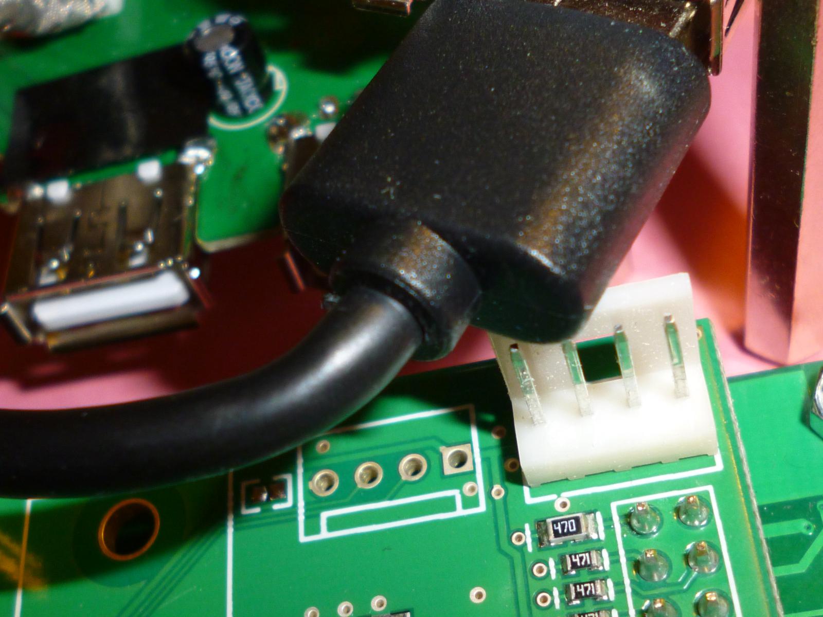
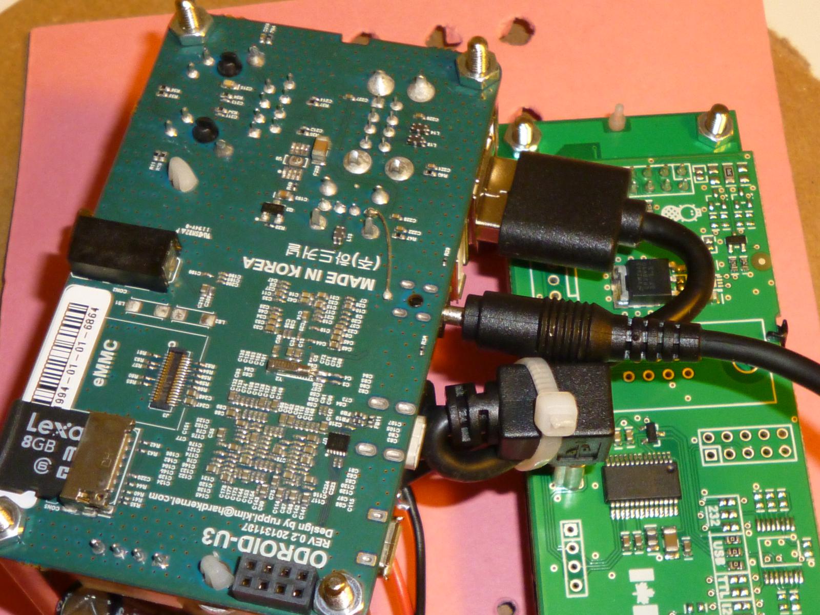
connector interference
Attaching all the components to a cardboard model of the front panel to check fit; here's one of the problems that turned up. One of the USB connectors on the ODROID attempts to pass through the same space as the aux power on the LCD panel. There's not enough wiggle room to move the ODROID into an orientation where this won't happen, because of other things that would interfere with each other in almost any other position.
The USB connection is necessary, but the aux power on the LCD isn't, so I was able to just cut that away and have enough room.
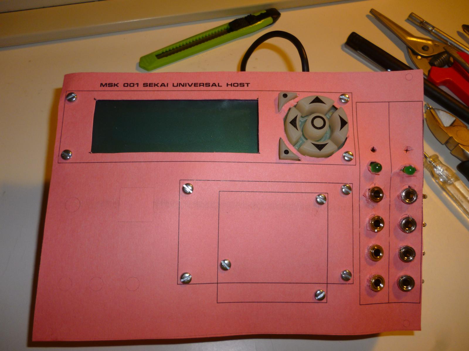
early mock-up front panel
Initially planned locations for the LCD, ODROID, USB hub, and two CVpals.
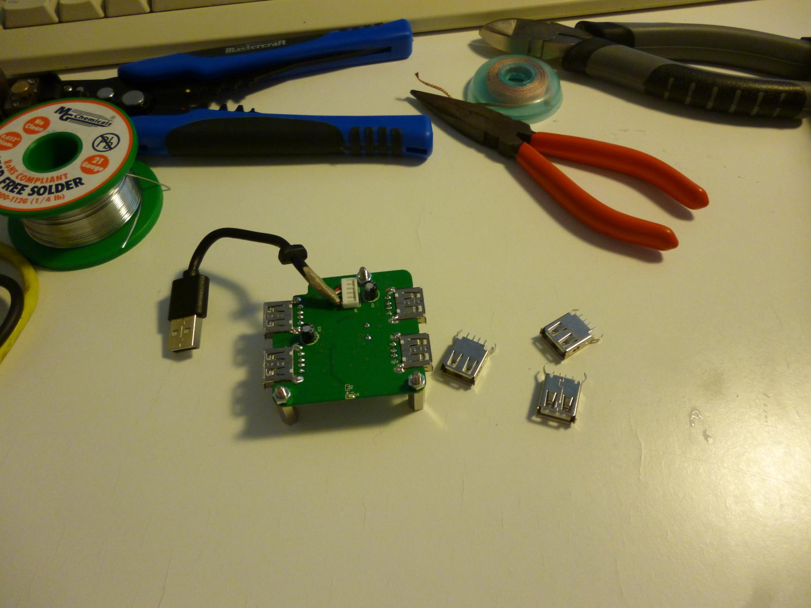
ready to modify the USB hub
This is the board out of a low-end four-port hub. The idea is that it get attached to the front panel between the panel and the ODROID - that's why the ODROID gets such long standoffs, and it's necessary to fit everything into 36HP. All four USB sockets on the board are coming off; one will be replaced by a captive mini-USB cable to plug into the LCD, and the other three will receive right-angle USB sockets that will be accessible from the front panel. Meanwhile the hub plugs into one of the ODROID's three USB ports, and the other two of those are filled by the captive cables on the CVpals. The hub also receives its own power feed directly from the distribution terminals instead of drawing all its power from the ODROID; that should relieve stress on the ODROID's power system, which I don't trust.
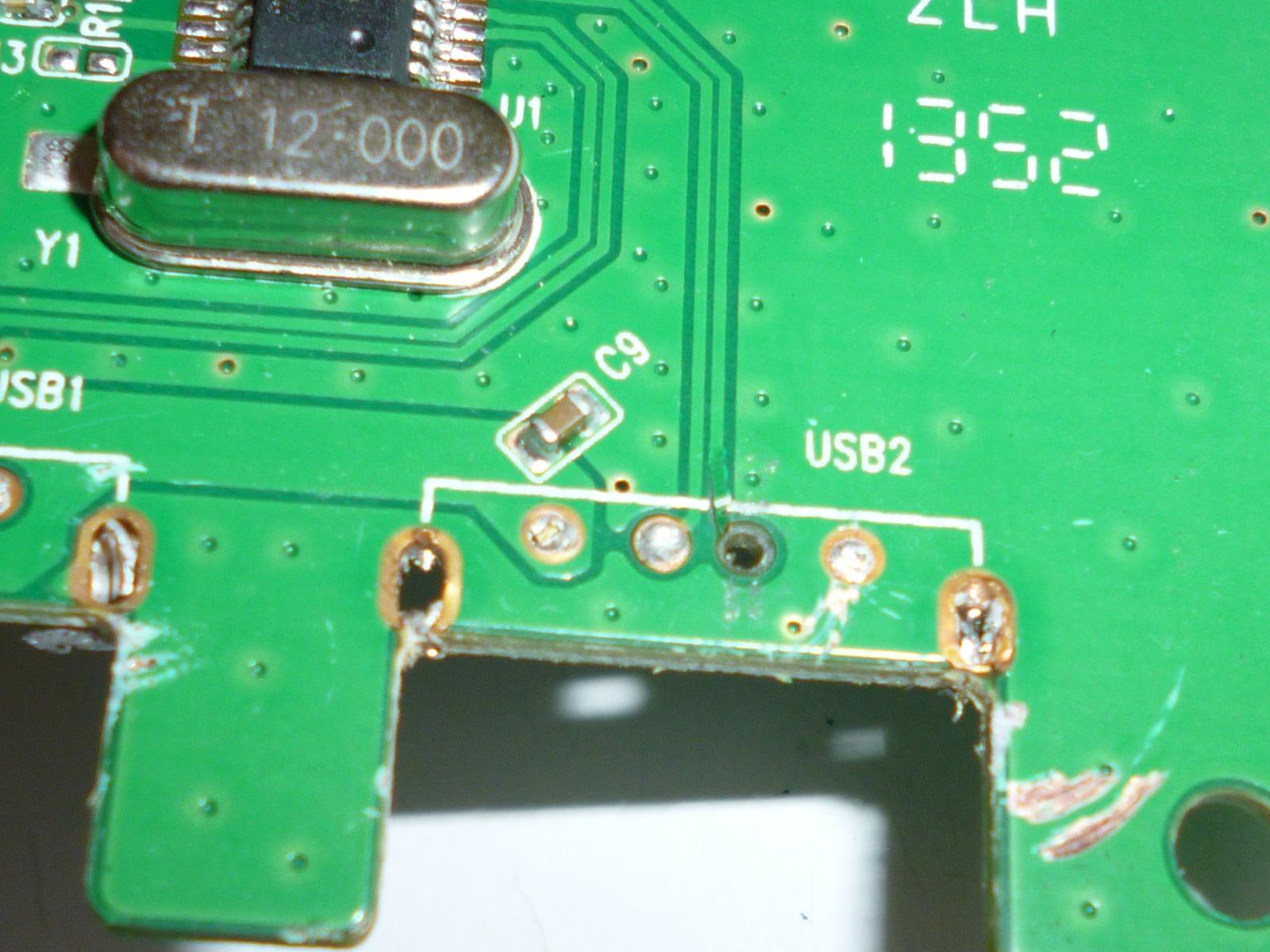
I had a hard time desoldering the sockets, mostly because the pins attached to ground (one contact and two shield tabs per socket) are connected to the ground plane on both sides of the board with no thermal relief and the copper ground planes suck the heat right out of the joint. It's nearly impossible to melt those joints with a low-power hand soldering iron. The result was that I ended up dumping enough heat into some other contacts, like the one shown here, that I delaminated the pads and through-hole plating right off the board. After considering different ways of trying to fix this, I decided to just throw out the board and get a new one as nearly identical as possible; bear in mind this was a cheap USB hub to begin with.
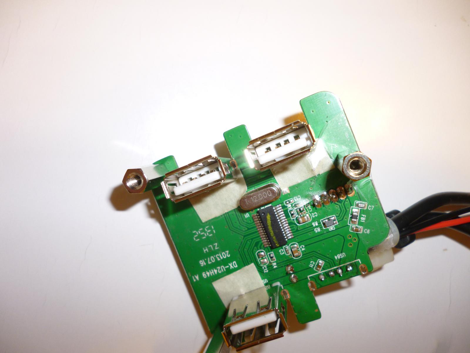
second USB hub, with replacement sockets
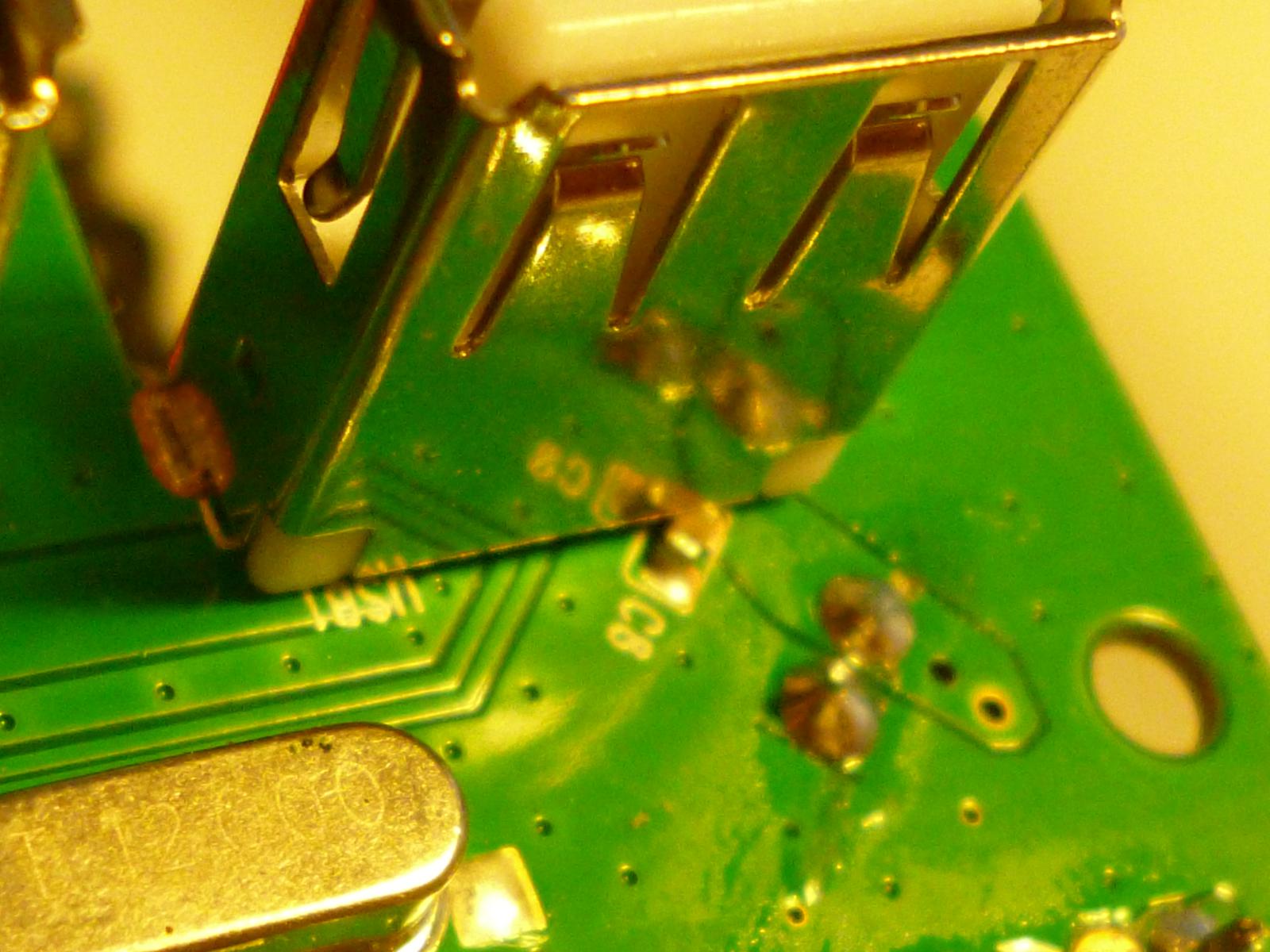
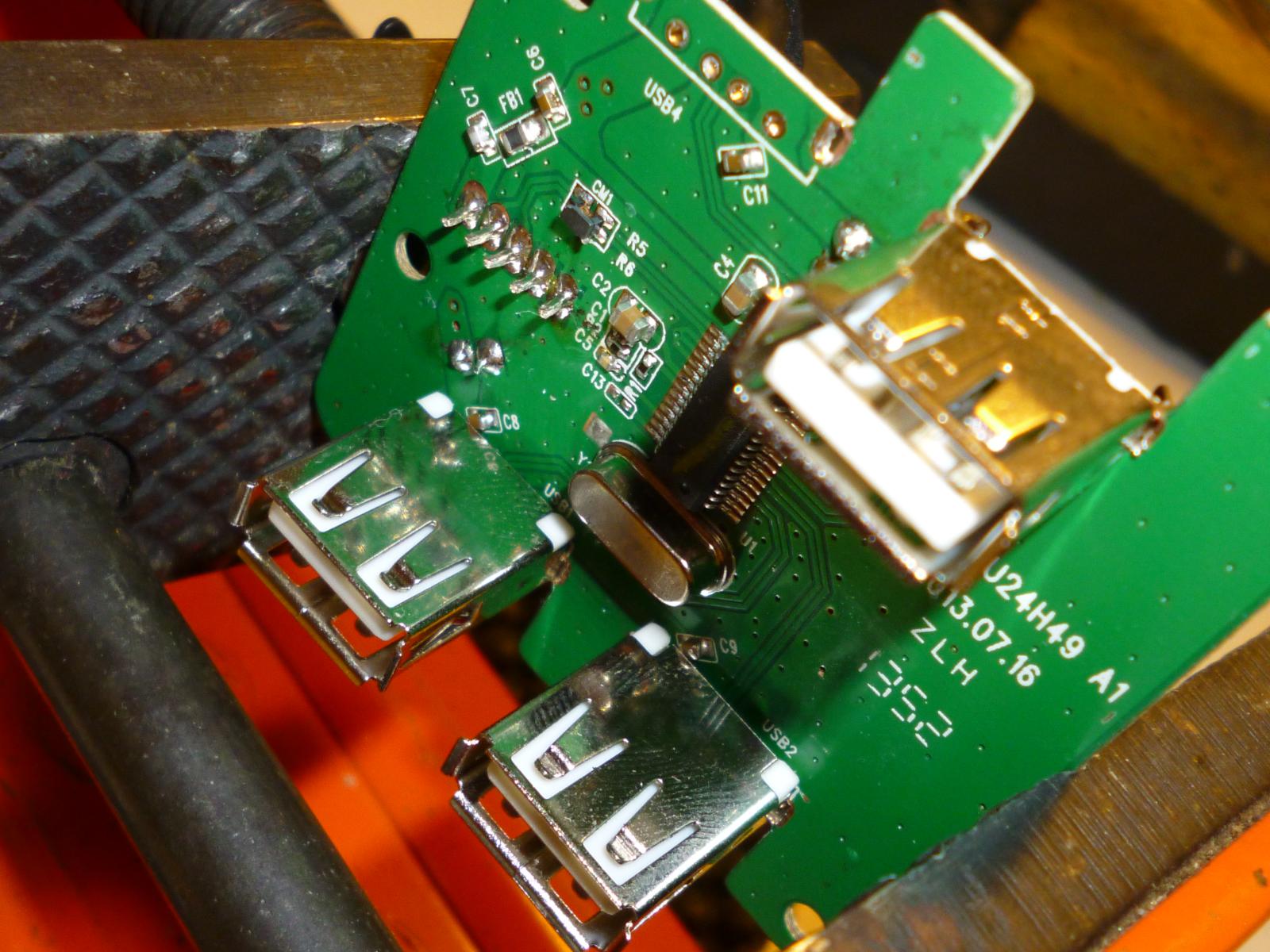
this will be trouble
I really should have noticed this before soldering it in place, but the grounded metal shield of the USB socket is resting nicely on the +5V pin of that decoupling capacitor (the one labelled C8). If it makes electrical contact it will short the power supply right out. But maybe, I hoped, it won't really make electrical contact. After my previous adventures I *really* didn't want to have to desolder another USB socket, especially because I didn't have any spares and so (unlike the origianl sockets, which I destroyed while removing) this one I'd be trying to preserve in usable condition.
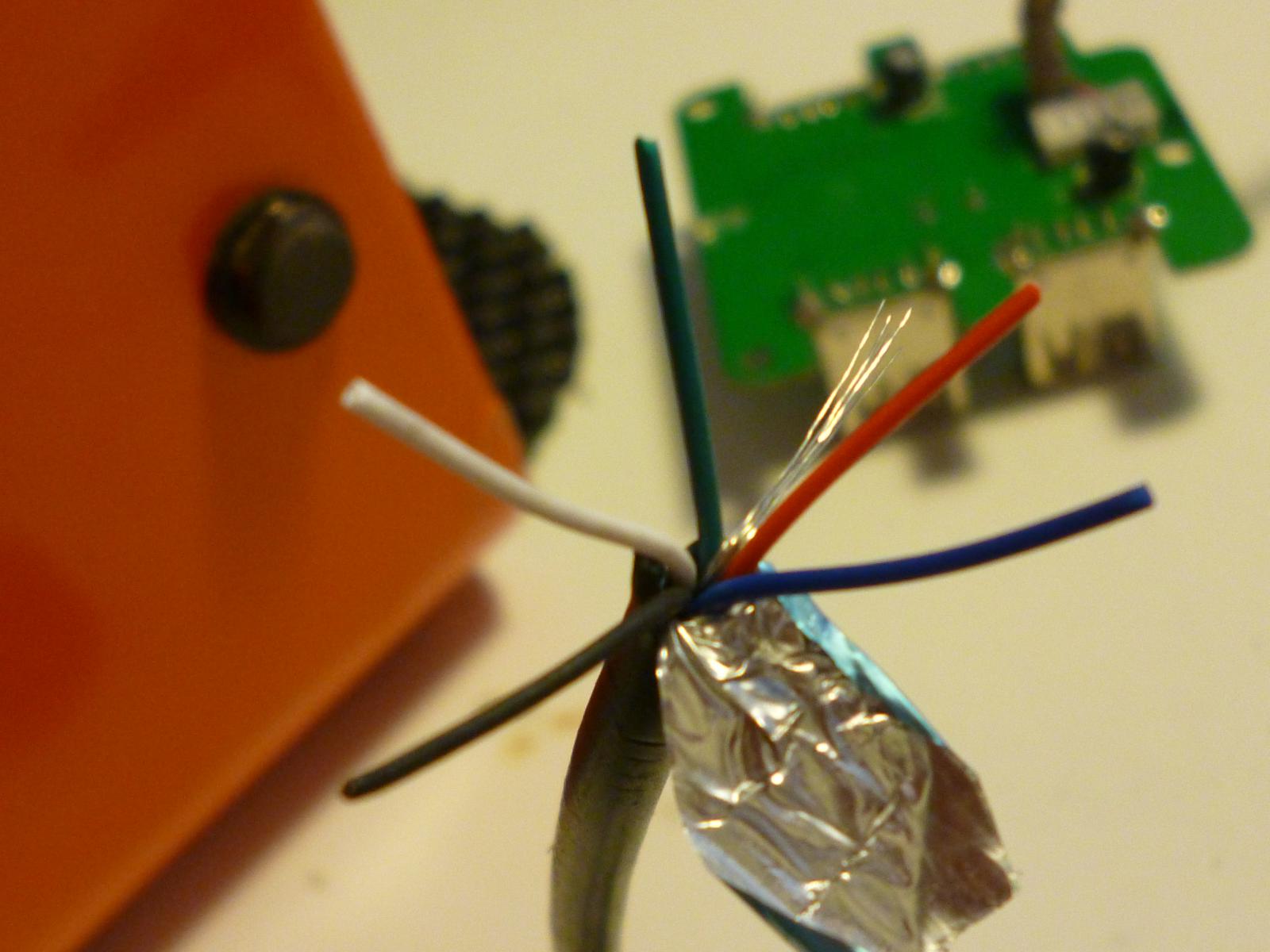
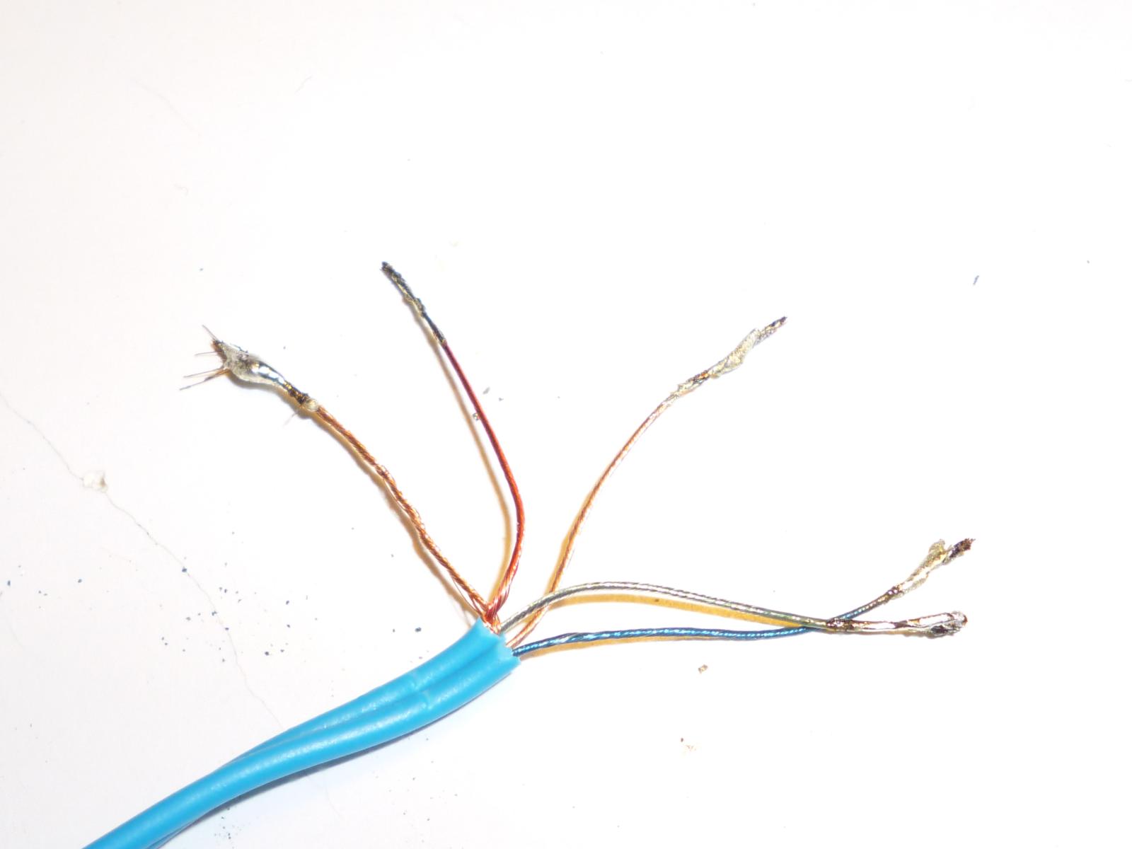
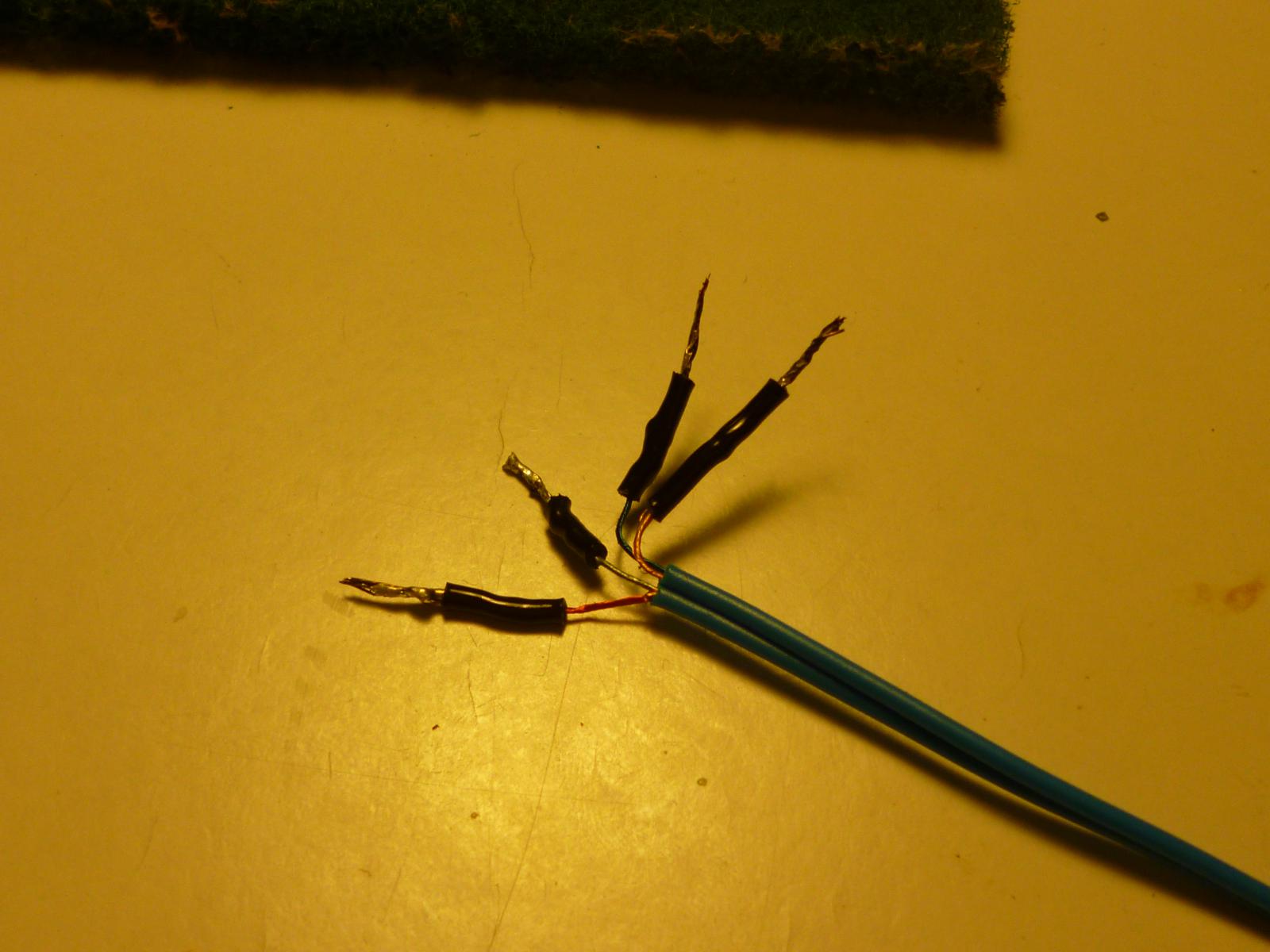
more impending doom
This is meant to be the captive cable from the hub to the LCD. Five, count 'em, insulated wires, plus shield foil and uninsulated grounding strands. Standard USB cables are only supposed to have four wires - black, red, green, and white. So what's up with the blue one? I guessed that it was for the "extra" contact in the mini-USB connector and I could leave it unconnected. That turned out to be the wrong guess; actually, the blue wire is the ground and the *black* wire is the one that it's safe to leave unconnected. So after soldering this in place and doing some testing, I had to eventually desolder it and rearrange the connections.
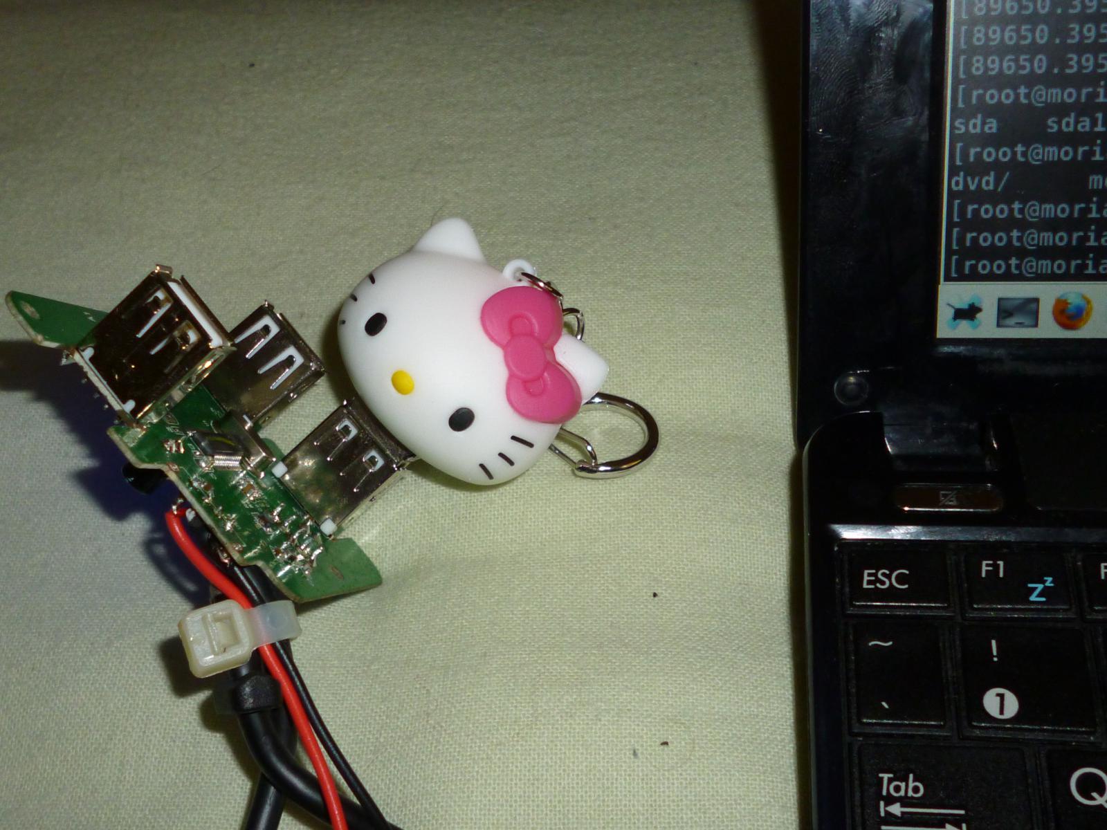
testing the hub
The severed head of Hello Kitty is a USB drive, being used to test the ports on the hub. It's a good thing that I did this testing with the laptop instead of the desktop computer, because it turns out that that shorting capacitor I was worried about *was* a problem. If I very gently plugged Kitty into the board, it would usually work okay; but any wiggling or extra pressure would cause the shield to make contact with the capacitor, shorting the power, and the laptop's reaction to a momentary short of the USB power was to immediately shut itself down. So this would have to be fixed in some way.
insulators added to hub
An attempt at solving the shorting problem without desoldering the USB connectors: varnished-paper insulators wedged between each shield and any components below.
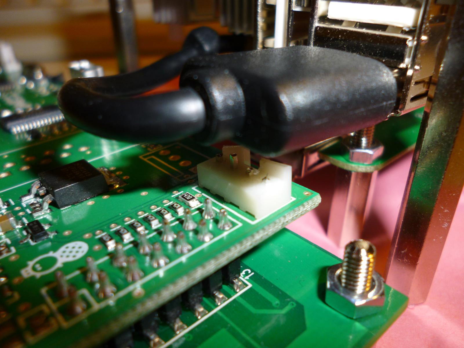
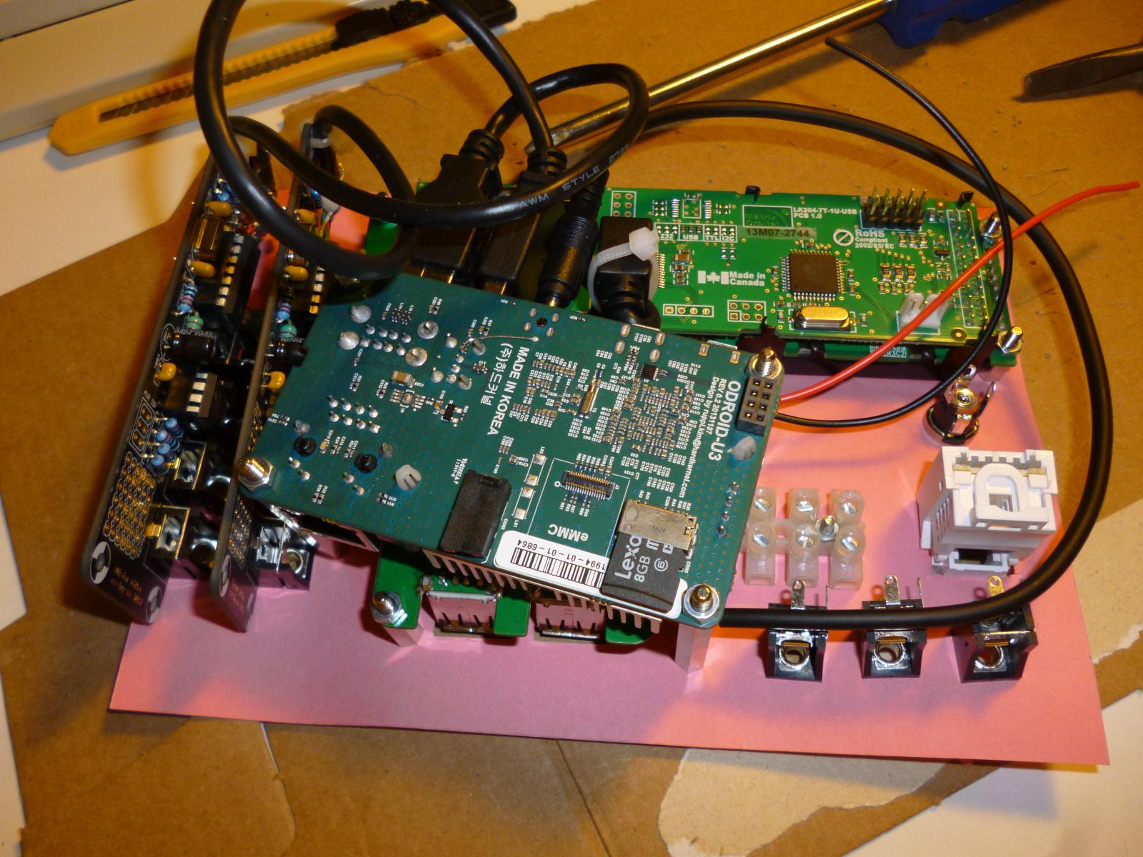
later mockup, from the back
Note I've changed the mounting for the ODROID to be oblique, which was necessary to get the mini-USB connector for the LCD module to fit. Even so, there is some strain on these connectors, in a way that is probably unhealthy.
later mockup with all front-panel parts installed
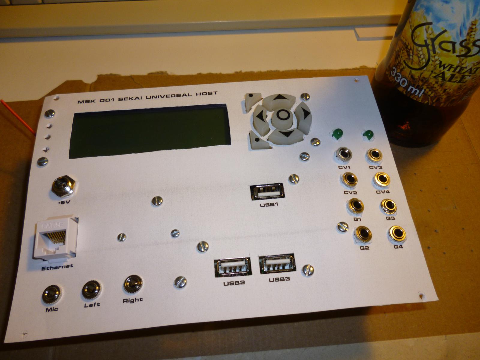
final mockup, from the front
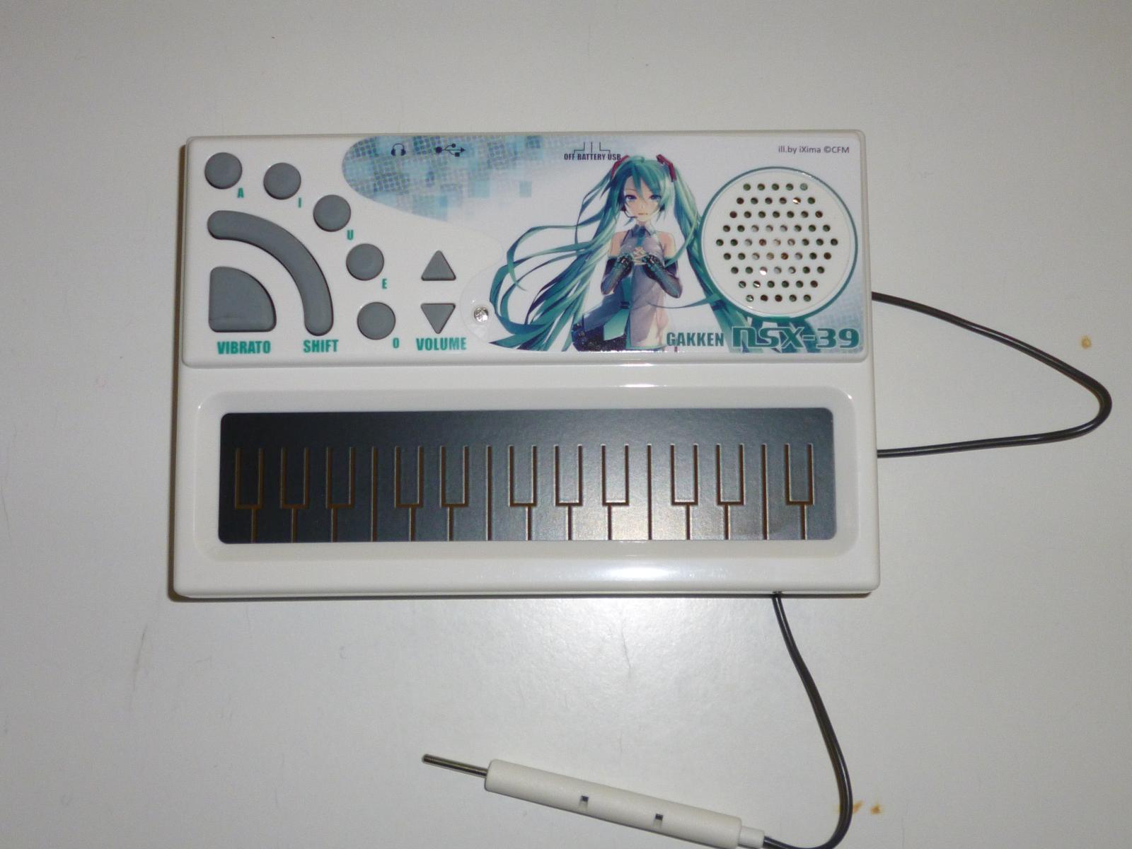
Gakken NSX-39 Pocket Miku
Not a do-it-yourself project, but this is one of the things I want to be able to attach to those USB ports on the front of the MSK 001.
![refinished end cheeks installed on the Cell[90] cases](https://ansuz.sooke.bc.ca/images/2014-06/P1020299.jpg)
refinished end cheeks installed on the Cell[90] cases
I later had to disassemble this (at the cost of scratching my lovely varnish, but fortunately only in inside places that won't show once the modules are installed) to reverse the position of the lower Cell[90] case, because with the power connections as shown, it's impossible to connect the power supply to the lower case. A plug plugged into the lower row's power socket would have to pass through the wall of the upper row. Never mind that the instruction manual, which I didn't consult before assembly, recommends installing them with the power connectors facing each other (i.e. the lower row as shown here and the upper row reversed), in which configuration BOTH rows would become impossible to use.
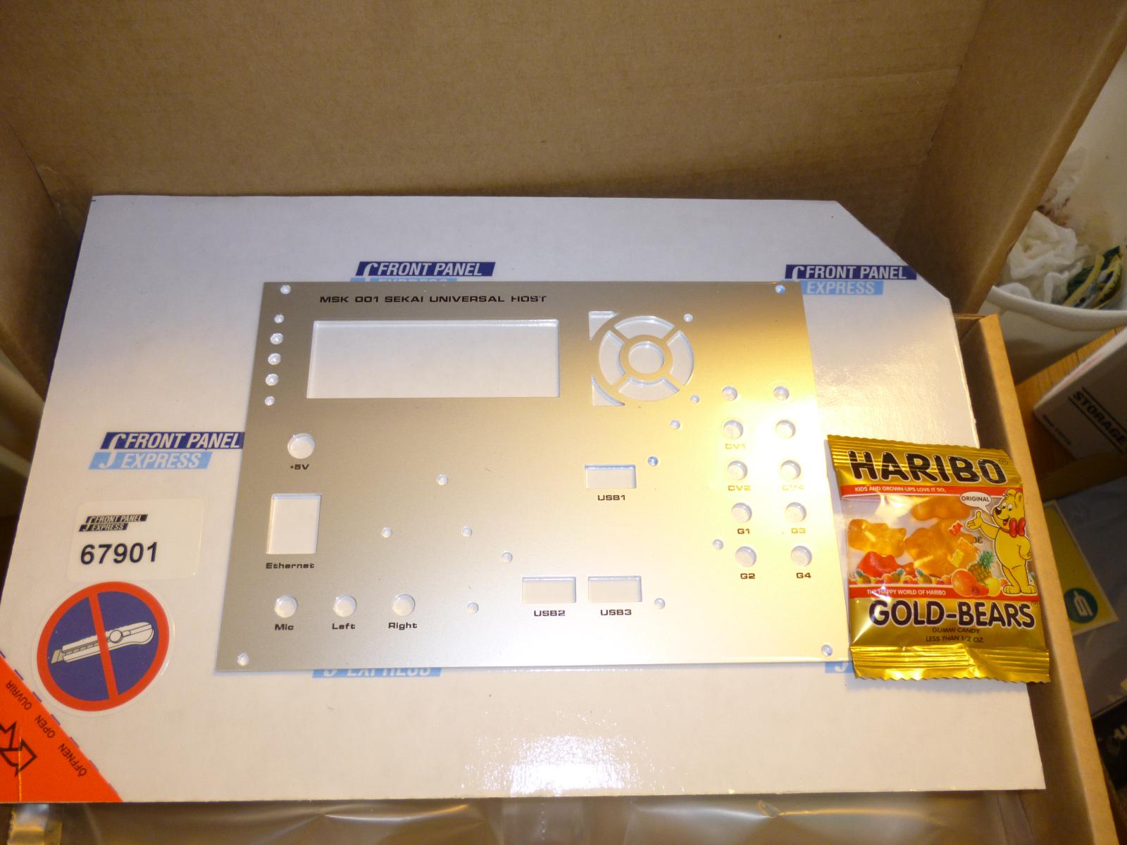
brand new front panel
I splurged on getting it done up properly by Front Panel Express - holes, engraving, and infill - instead of trying to fabricate the whole thing myself or do my own printing or infill. Not sure I'd go this route every time, but it seemed reasonable on this particular project. At the very least, those odd-shaped cutouts for the LCD module's pushbuttons would have been unpleasant to do by hand. FPE showed their appreciation by including free gummy bears - and sending me a thank-you card a couple weeks later.
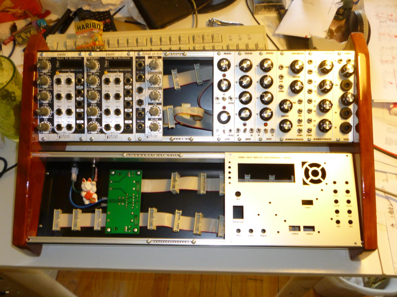
front panel in position to see how it looks
I really wanted the MSK 001 to go at the left, not the right, of the bottom row; but because of the power supply there wouldn't be enough depth for the completed MSK 001 module on that side. But remember what I said a couple images back about turning the lower row around... this picture was taken before I discovered that that would be necessary. Note the 14HP hole crying out to be filled in the upper row.

most parts in place, but not wired up
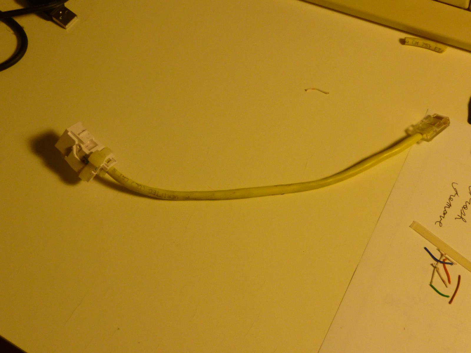
Ethernet extension
The little end plugs into the ODROID's Ethernet jack and the big end is a keystone Ethernet socket that's supposed to snap into the front panel. Unfortunately, it doesn't really snap in place very solidly, probably because the 2mm panel is too thick for the snaps to work properly. I'm not sure if I'm going to be able to come up with a better way of keeping it in place, or just live with the fact that I have to be very careful inserting and removing cables in that socket.
tinsel soldering practice run
The ODROID's audio connection is a cell-phone-style (Samsung, not Apple, pinout... this is important) TRRS connector. It takes what looks like a 1/8" stereo plug with an extra ring around it, to connect left and right outputs and microphone as well as ground. Male connectors of this type are hard to find, especially if you want a right-angled one (which was necessary for me because of the cramped space inside the modular case). I ended up buying the cheapest pair of earbuds with built-in microphone that I could find with a right-angled TRRS plug, and cutting off a chunk of cable attached to the plug. But that necessitated soldering to the horrible tinsel wires inside the cable. Shown here is a practice run with another chunk of the cable, in which I was trying to learn the technique of tinning the tinsel wires to get a decent connection out of them. Of course this was all done with lead-free hippie solder, which only makes it all even more tricky.
final soldered tinsels
Final version of the soldered tinsel wires. I ended up attaching small chunks of regular stranded copper wire to the end, so as to have something sturdier than tinsel to screw into the Euro-strip terminal block. And I put small-diameter heat-shrink over the connections, both to provide at least a little strain relief, and to hide the shame of the ugly tinsel-to-stranded soldering connections. I'm probably not going to win any NASA contracts with this one.
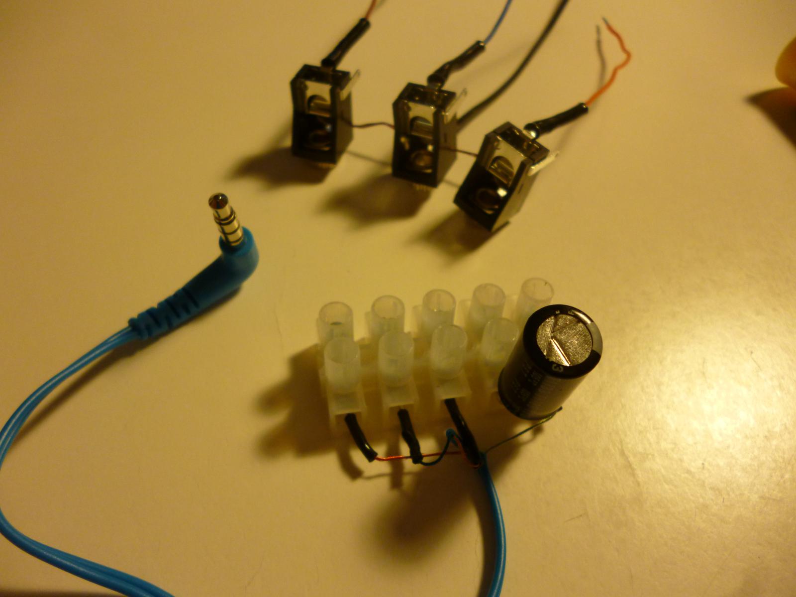
some front-panel components
Here it doesn't look too too bad. I ended up having to rearrange the tinsel connections because I'd guessed wrong about the pinout of the damn TRRS connector. In the background, three mono jacks for left, right, and microphone audio connections.
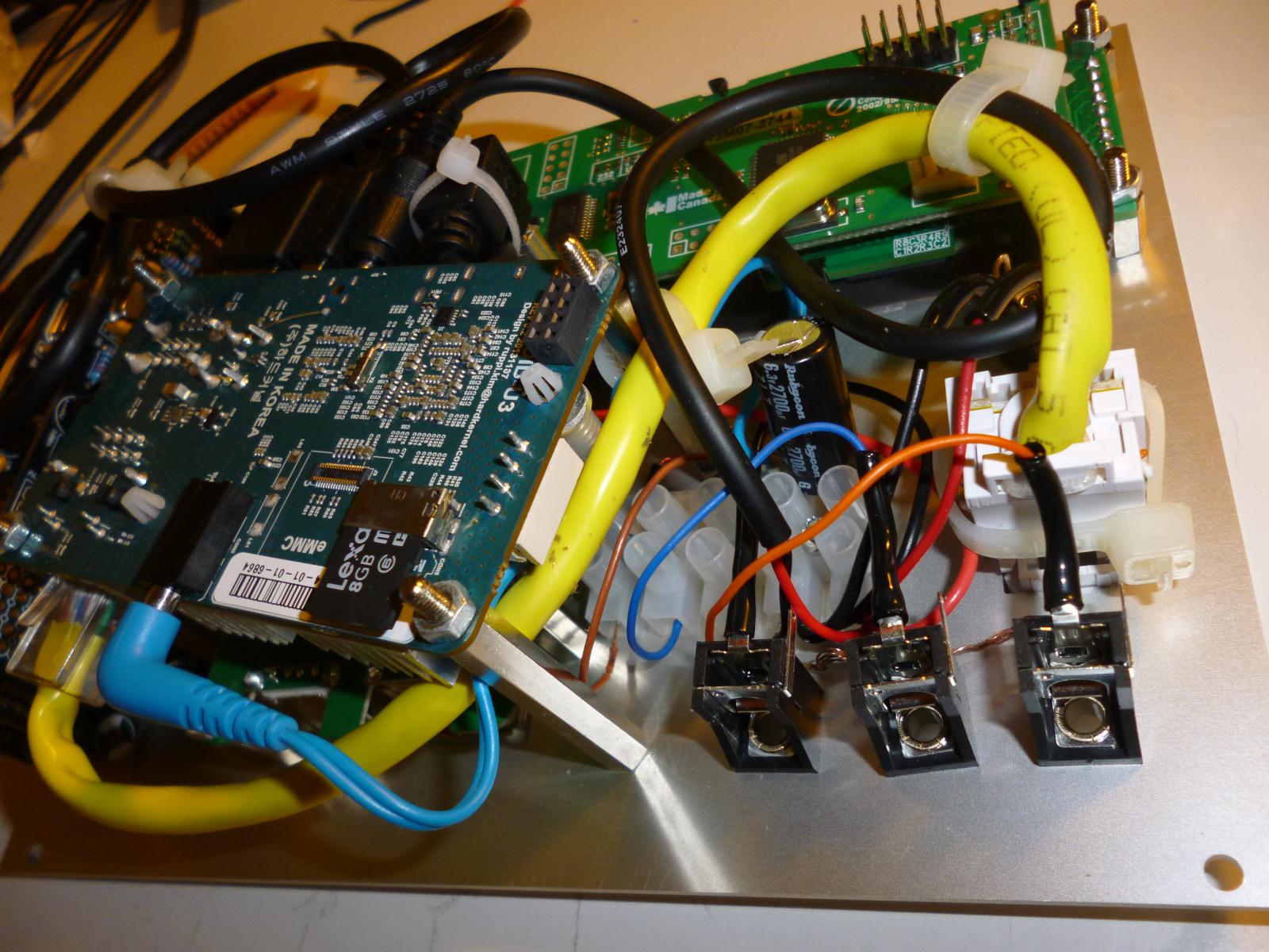
everything wired up
Not visible from this angle is the dead short right across the power supply, because of a power wire stripped a little too far and resting on a bare grounding wire, in the cramped space around the Euro-strip terminals at bottom centre. Good thing the power supply I plugged into it has short-circuit protection.
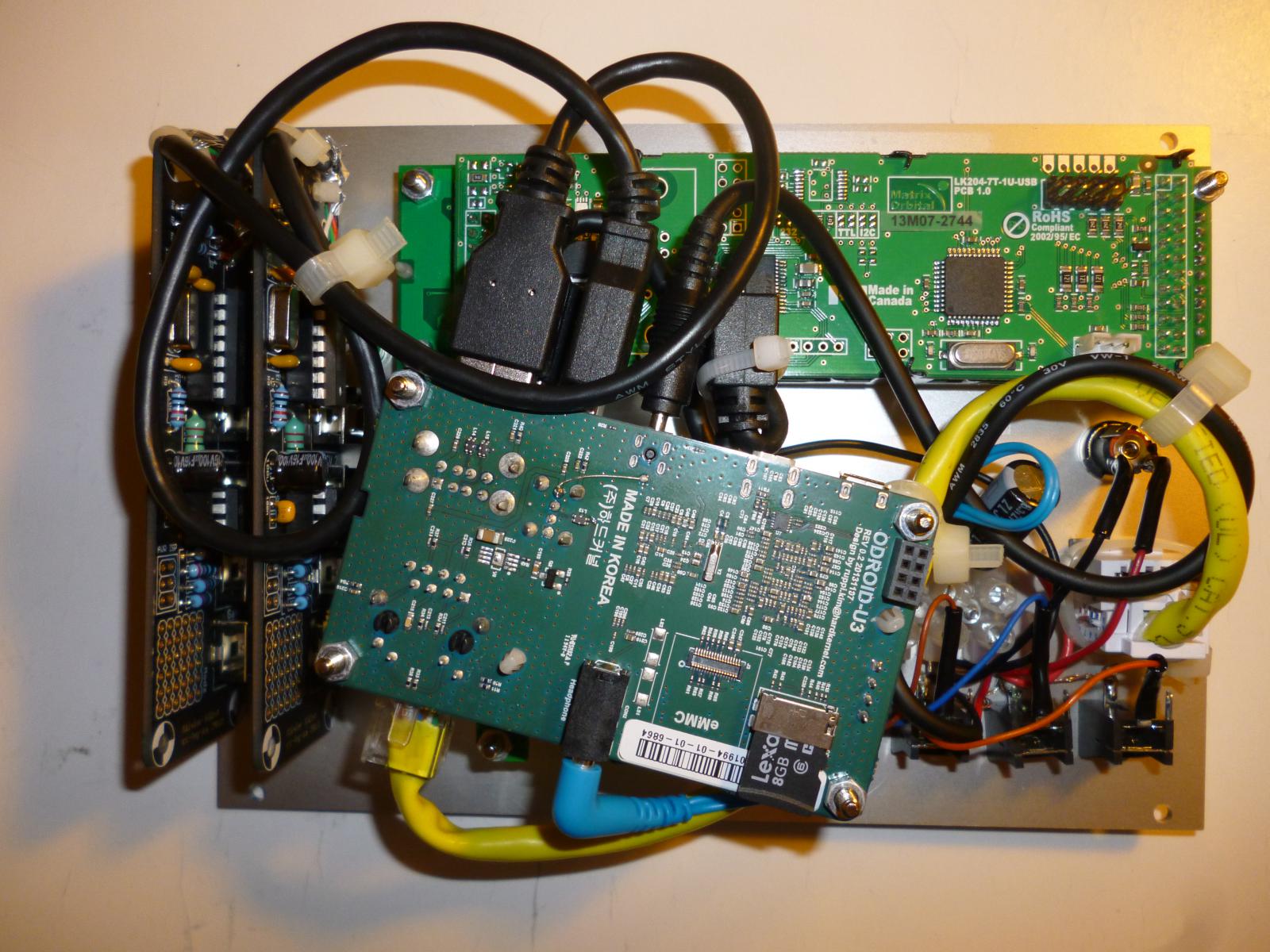
rear view of assembled module
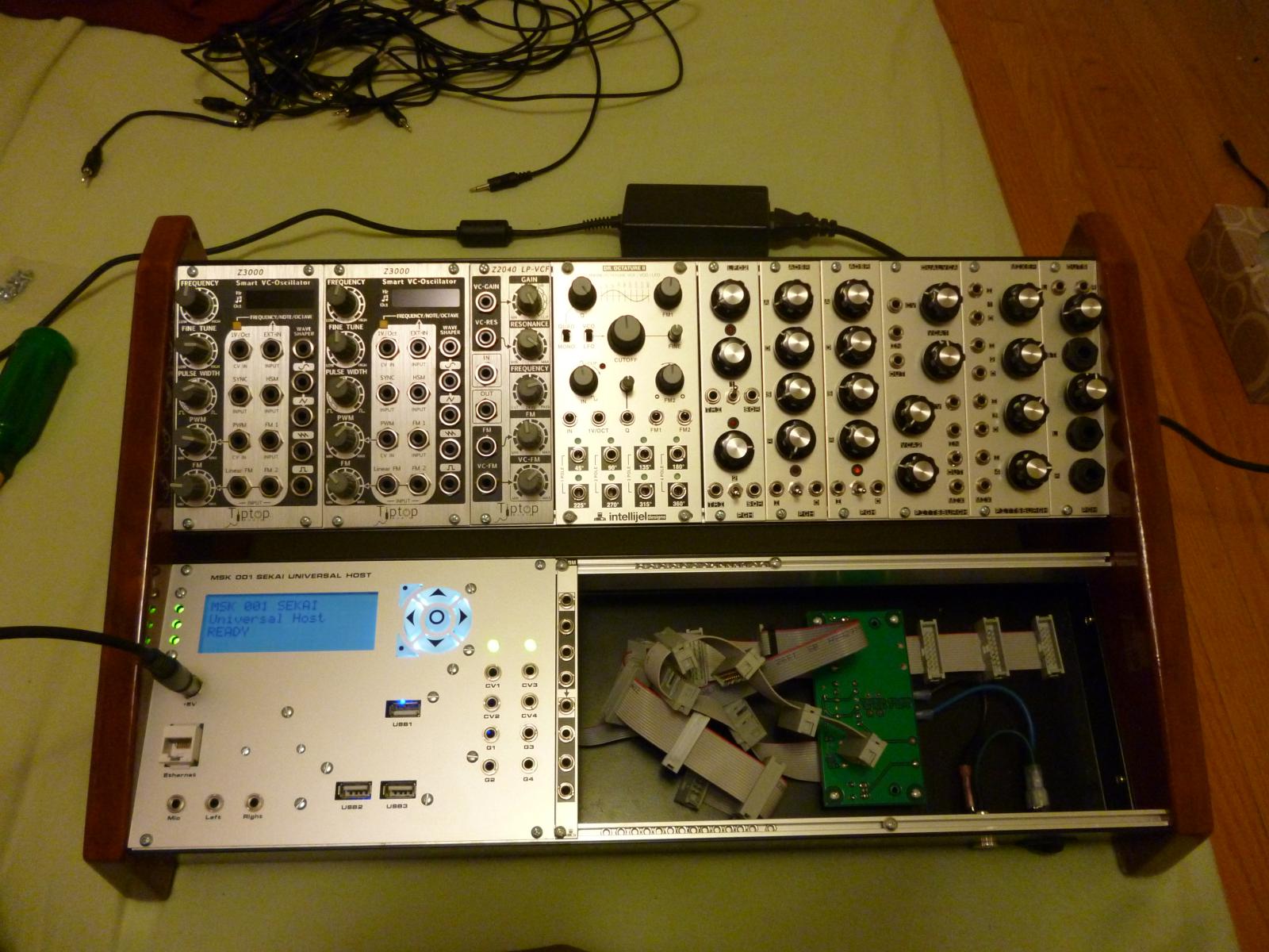
module installed and operating
Note that in this image, the lower-row case has been turned around. Also, I found something nice to fill that 14HP hole in the upper row...
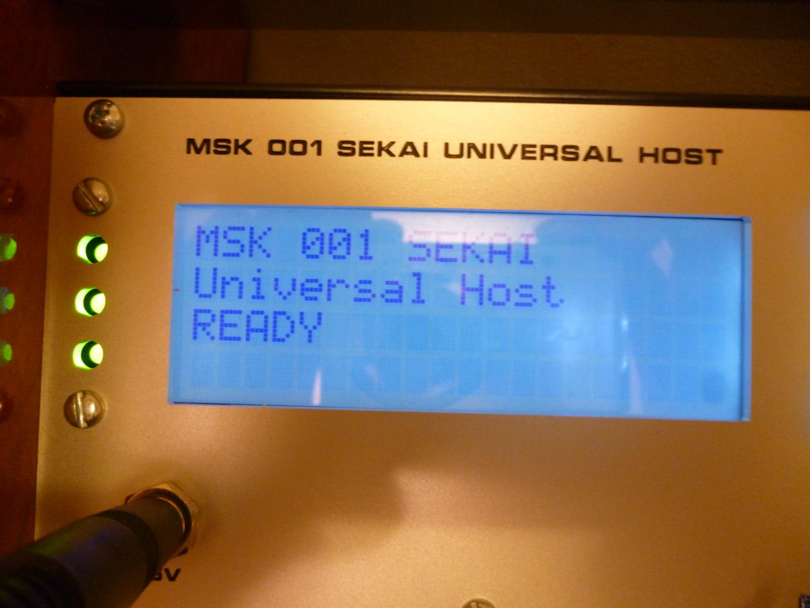
Universal Host READY

0 comments