LCD monitor adventures
Mon 23 Jul 2012 by mskala Tags used: hardwareI haven't had very good luck with computer hardware, nor operating systems, in the last few months. I lost a hard drive in my main desktop computer at home, and had to replace that (no data loss because it waS RAIDed); the latest Arch Linux "upgrade" made my computer unbootable because the maintainers decided they had to move everything from /lib into /usr/lib and the documented procedure for doing the upgrade safely didn't cover oddball configuration cases like having GCC installed (because who would have that?); and now my LCD monitor is dying.
It's an LG L206WTQ-BF, manufactured January 2008. The symptoms are that when powering up (either from full shutdown or power-save mode) it takes a long time to start. The power light (which is solid orange in power-save mode, solid blue when fully turned on) goes blinking blue and the screen remains blank for about fifteen minutes. Then the logo appears as it would in a normal startup; sometimes the logo appears and disappears a couple times over the course of two or three seconds; and then the monitor works normally.
This is a fairly well-known and well-understood failure mode with these kinds of monitors: it's almost certainly a bad electrolytic capacitor in the power supply. The critical part of this kind of capacitor is a very thin layer of aluminum oxide on the surface of a rolled-up piece of foil. The oxide layer is a little bit unstable; it is created and maintained by the interaction of the aluminum with a water-based caustic electrolyte solution. Over the course of a few years, and this is likely to happen sooner and more likely to happen at all if the capacitor was a cheap one, the electrolye can leak out or dry up. When that happens, the capacitor can still sort of function as long as the device is turned on, because the voltage across the capacitor helps maintain the oxide layer. But when it's turned off, the oxide starts to dissolve into what's left of the electrolyte, and so when you turn it on again, it doesn't work. The power supply starts producing some voltage, but it's not enough, or not stable enough, for the computer inside the monitor to start up.
However, as it sits there trying, the supply voltage across the capacitor starts regenerating the oxide layer until eventually it reaches a usable condition. Then the voltage rises and stabilizes and the controller can start and then it's fine as long as it remains turned on. When it's turned off, the oxide starts to degrade and the cycle starts over again. This model explains some details like the fact that if it's only turned off a few minutes, then it can start again promptly, but the longer it's turned off the longer it will take to start the next time.
So, I know what's wrong. The question is what to do about it. In the short term I guess I could just never power it down at all, but that's obviously not a good long-term solution. Given the cost of labour, in comparison to the value of a used monitor of this size and age, it seems unlikely I can hire someone to repair it for a price that makes sense. It goes against my grain to throw out a machine that still works except for a simple replaceable part. These considerations point toward the idea of fixing it myself.
However, it's going to be a lot of work to disassemble it, and I have to do that before I can even look at the capacitors. Then the sensible thing to do is replace all the electrolytic capacitors in the power supply, because unless one is visibly leaking I'd have to unsolder them to test or precisely identify them anyway, it may not be possible to reliably determine which one is bad even with them unsoldered, and even if only one is bad, the fact that one went bad means the others are probably close. Then there's the question of where to get replacements. I've got a lot of miscellaneous electronic components lying around, but there's no guarantee I'll have a good match to the bad ones, and any matching spares I may have will themselves be years old (and likely salvaged from other things, not new). I don't want to go through putting in replacement capacitors that will just die again next year; the cost of my own labour, even though I don't pay money for it, makes that a bad proposition.
All in all, it looks like what I have to is disassemble the monitor, unsolder all the electrolytic capacitors in the power supply, buy replacements for all of them mail-order (which entails a wait of a few days), install those, and put it back together. And I won't know for sure that I did it right, and that this really was the problem, and that this was the only problem, until the end of that whole process.
So, that's what I guess I'll do. I am typing this on my laptop, logged in across the home LAN to my main desktop computer. The computer itself will remain functional unless something else goes wrong, but it looks like I have to do without a monitor for a few days. I'm going to post photos of my progress as I'm working on it, both because they'll be interesting and to help record where all the parts go for reassembly.
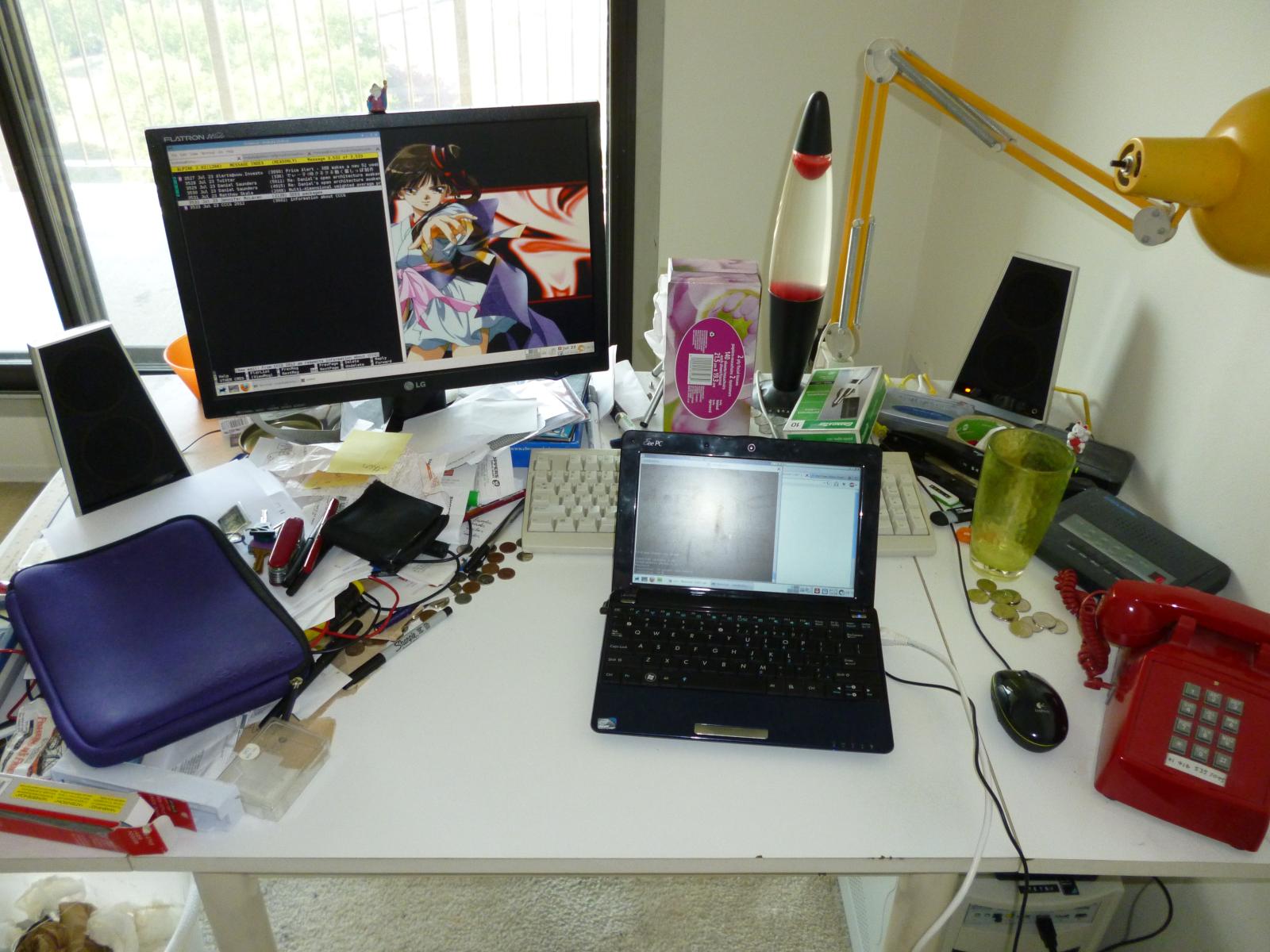
始めている・ready to start
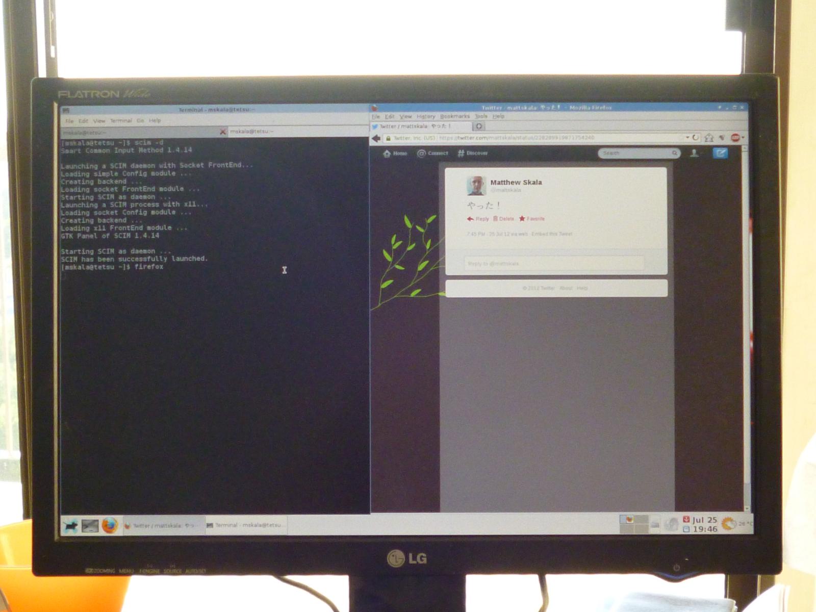
The monitor, at left, is the bad one. It's working fine at the moment shown in the photo, but it took over 15 minutes to start up and the delay seems to be getting longer each time. It's obviously not going to be usable long-term if not repaired.
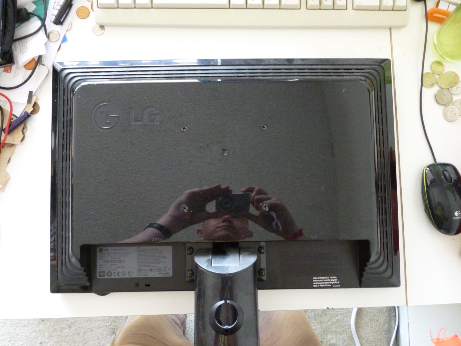
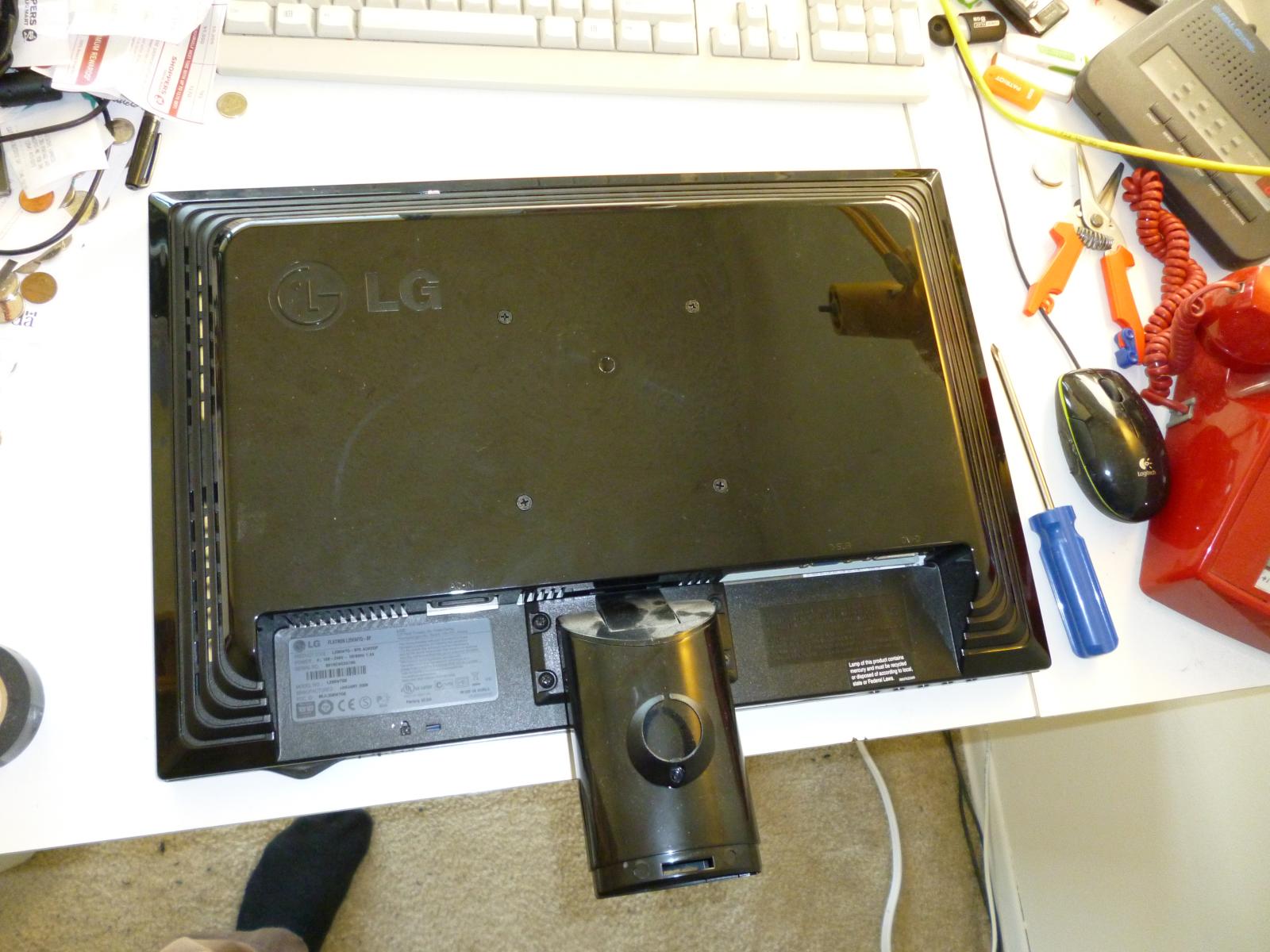
Here's the monitor face down on the table, ready to start the disassembly
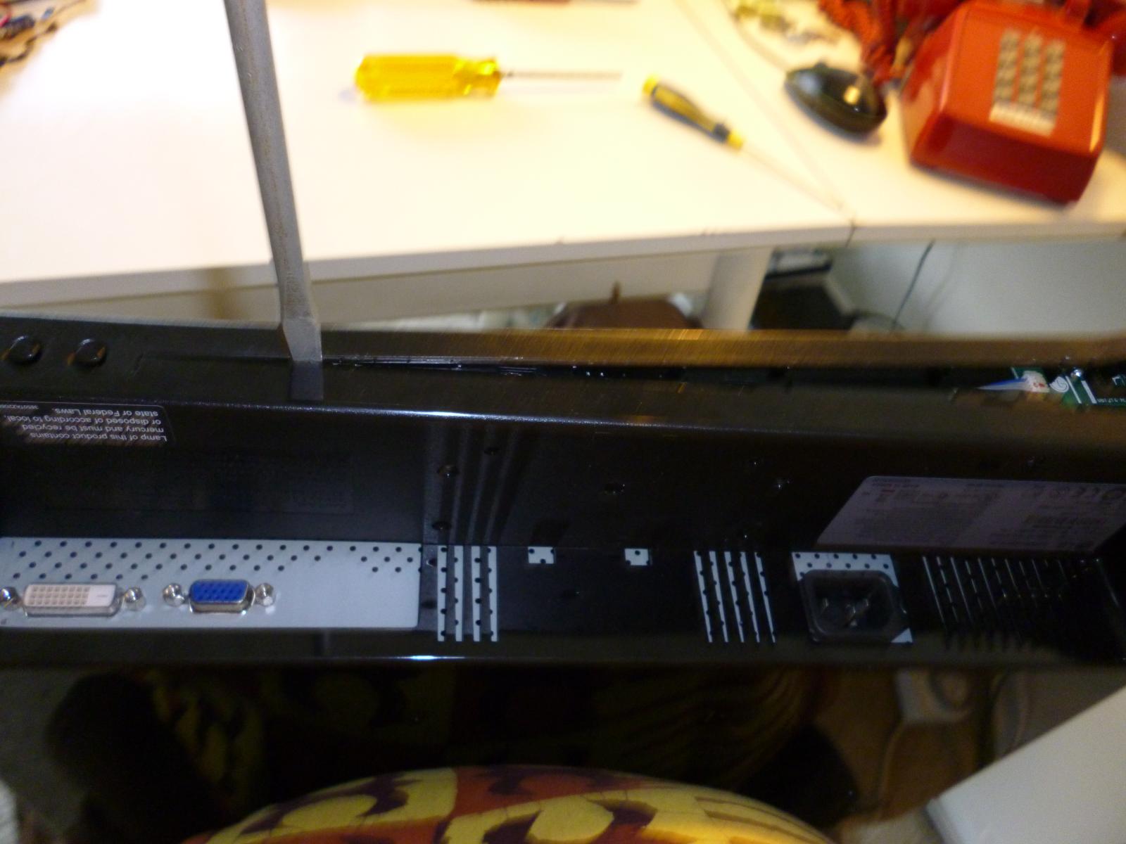
Almost finished prying the bezel off. This was (so far) the most frustrating part of the whole operation. The bezel is not intended to be removed *at all* once it's been snapped in place, and it's not really possible to remove it without damaging it. I managed not to create too many visible dings.
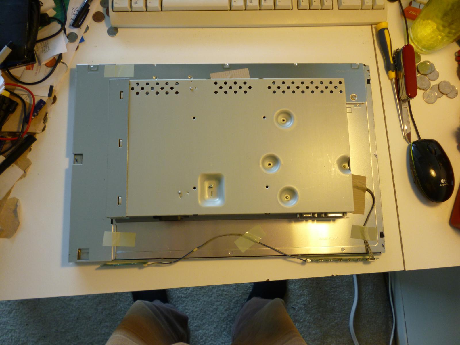
Monitor with the outer plastic case removed. Now several of the parts are held in place by a couple of different exotic Korean varieties of sticky tape, which, like the bezel, can't really be removed non-destructively; especially not after they've been baked in place by the heat of a few years of high-duty-cycle monitor operation.
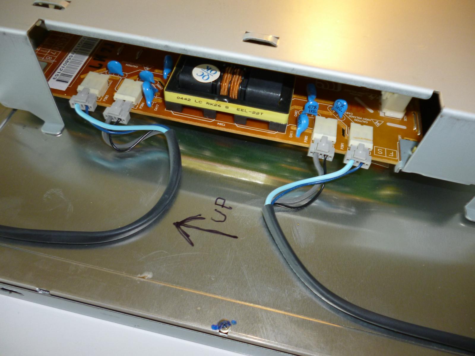
The first thing to disconnect, after removing the aluminum shield that covered them: these are the high-voltage plugs for the backlight. Photo is to help record which plug goes where, as is the felt-pen "UP" arrow.
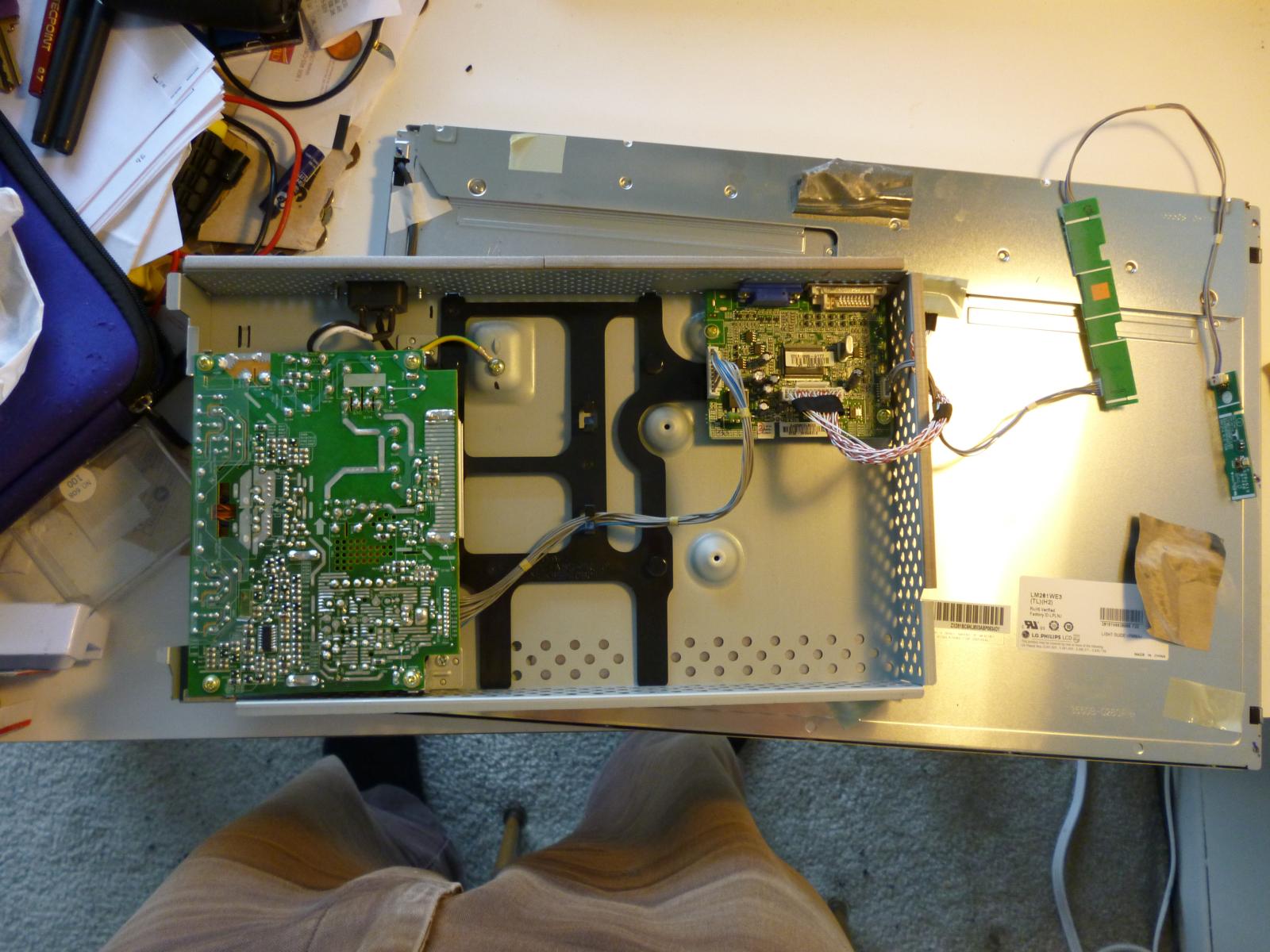
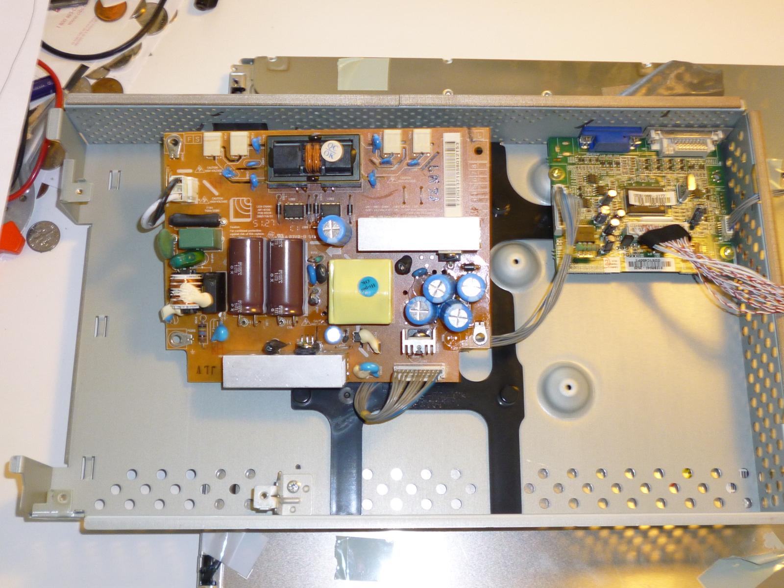
With the tape removed, it's now almost possible to separate the electronics box from the monitor panel itself. The only thing still holding them together is the multi-pair data cable near the centre. I tried to disconnect that, but it didn't seem easy to do while being sure of not damaging it, and since I didn't absolutely need to undo that connection, I decided to leave it in place. The part we're really interested in is the large green board at left: the power supply. It is held in place by four screws, a two-pin cable for AC power, and the multi-conductor grey cable that goes to the "brain" board in the centre.
Note how much empty space is in there. Wouldn't it be interesting to add a small-form-factor PC motherboard and some flash storage?
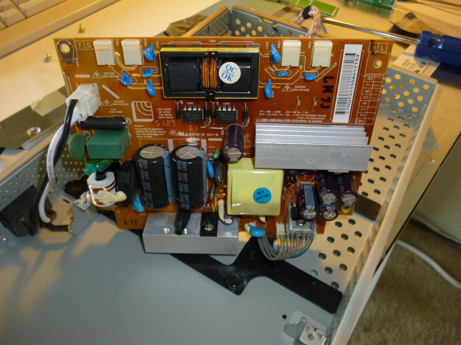
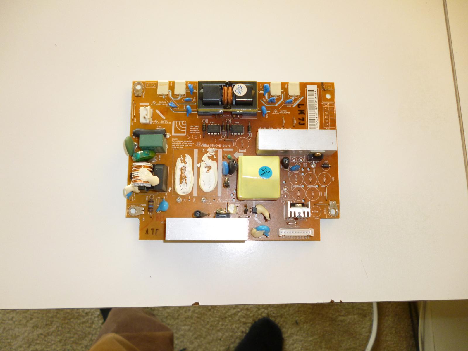
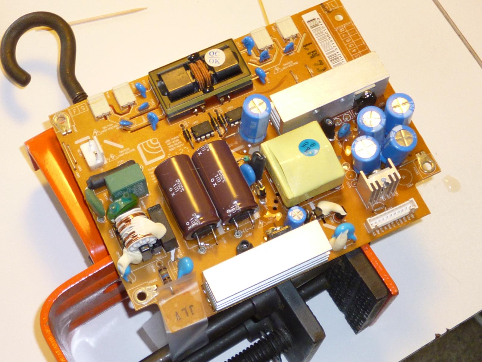
First view of the component side of the power supply board. The screws are undone but the cables are still connected. The electrolytic capacitors, guests of honour so to speak, are the purple-black cylinders. I found a Web page describing a similar repair to a nearly identical monitor and they recommended replacing the five 1000uF capacitors, which are the medium-sized ones; four in lower right and one near the centre of the board. However, there are also three other electrolytic capacitors on this board (two large ones and one small) and I intend to replace them ALL. Not doing so would be a foolish economy under the circumstances.
It was hard to get a good photo of this, but it's one thing obviously amiss: there is a plastic shield over the high-voltage section of the board, probably intended to prevent arcing, and it's held in place by two little feet that are glued to the board. Except one has come unglued and the whole shield is at a funny angle as a result. I'll glue it firmly in place when I reassemble the monitor.
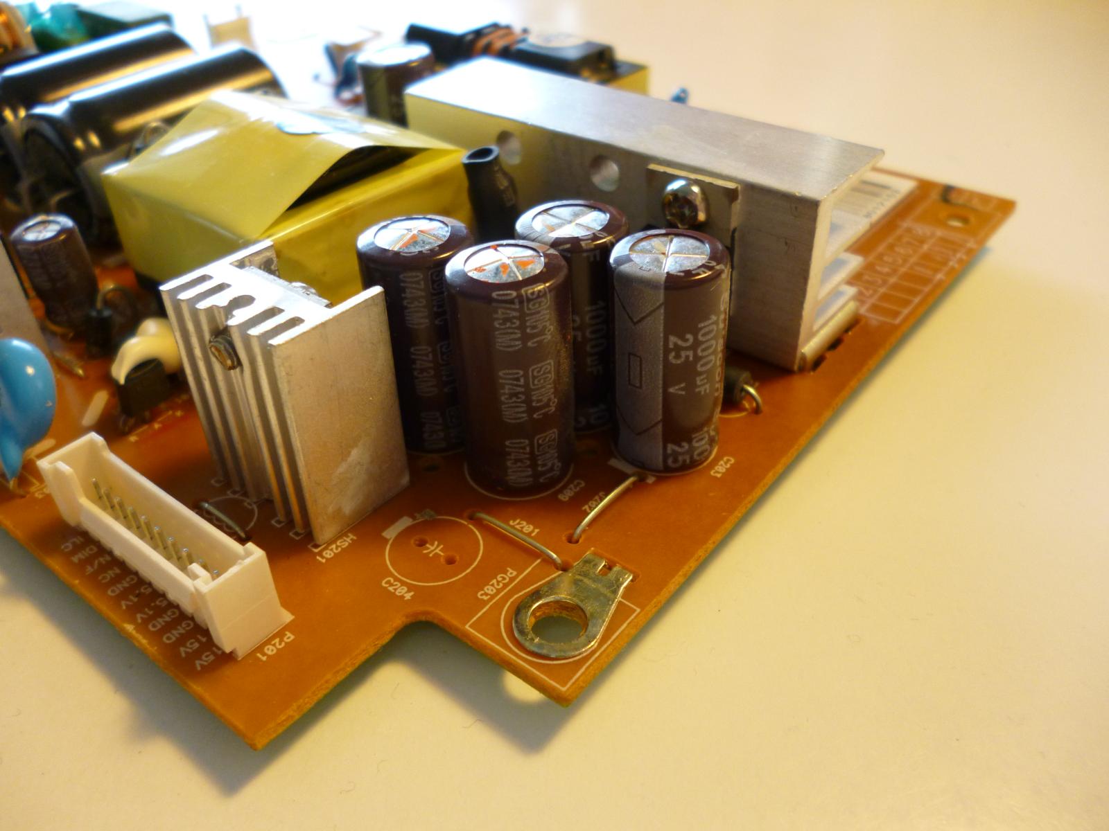
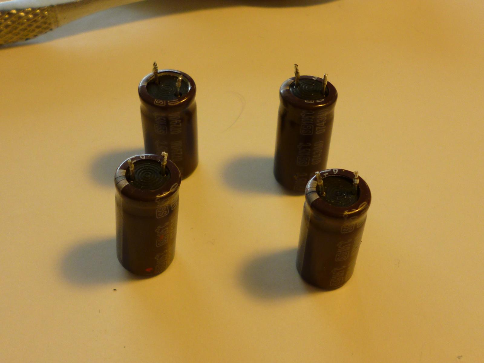
Close-up of four of the 1000uF capacitors. Two of these have a 25V rating and two 16V. Electrolytic capacitor voltage ratings are funny: normally you think of a voltage rating for a component as being the MAXIMUM voltage the component can tolerate, and it's true that an electrolytic capacitor will probably blow out if you run it much over its rated voltage. However, they also *need* voltage in order to maintain their dielectric layers. So if you run the capacitor significantly below its voltage rating, that will also cause it to fail eventually. You really need to get the voltage right, not "err on the safe side" with a higher rating.
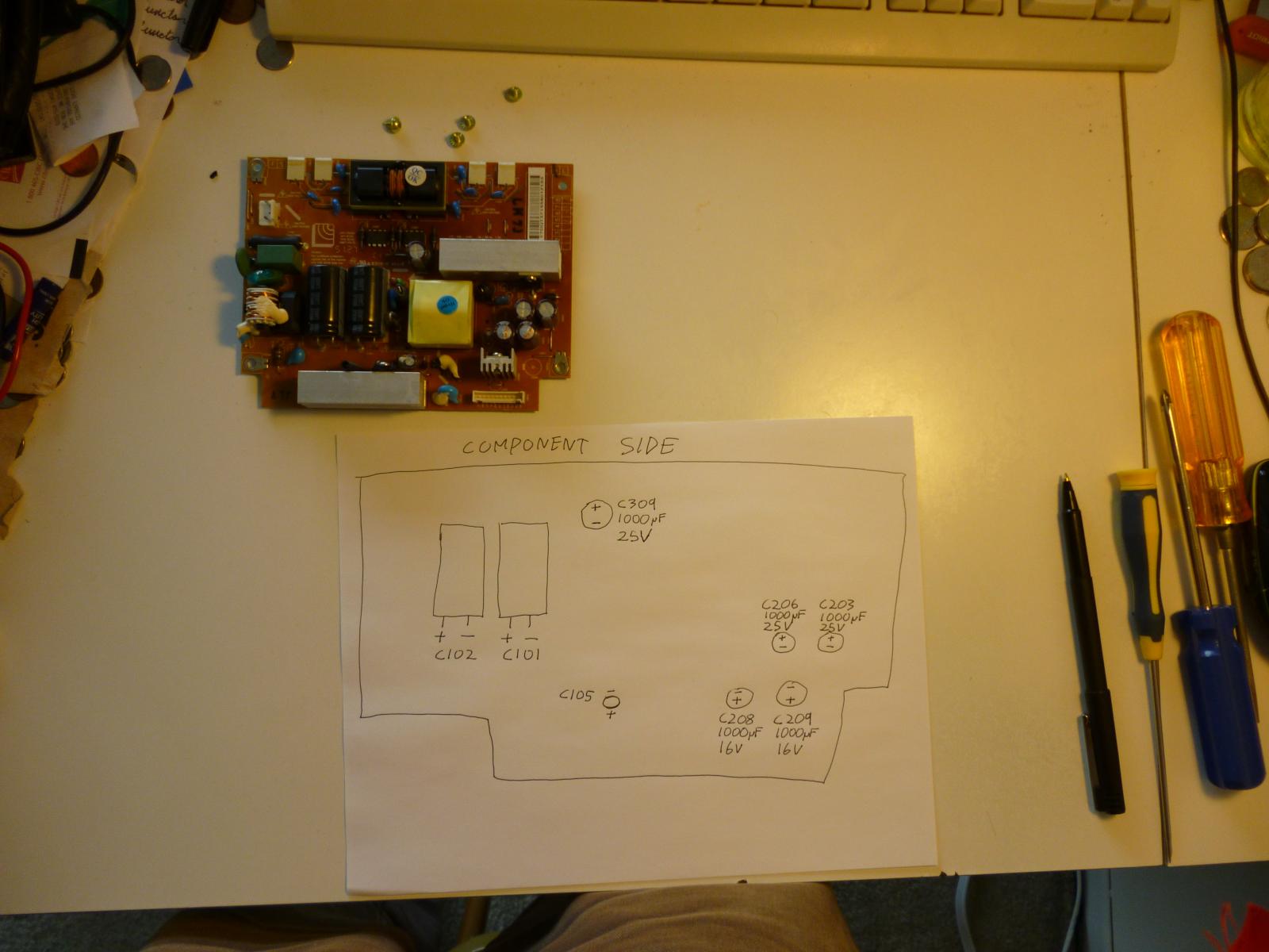
Power supply board with my notes on the ID numbers, capacitances, and voltage ratings of the eight capacitors I propose to remove. For C101, C102, and C105, the relevant parts of the labels are not visible because of the way the components are installed; I'll have to examine them carefully after I remove them.
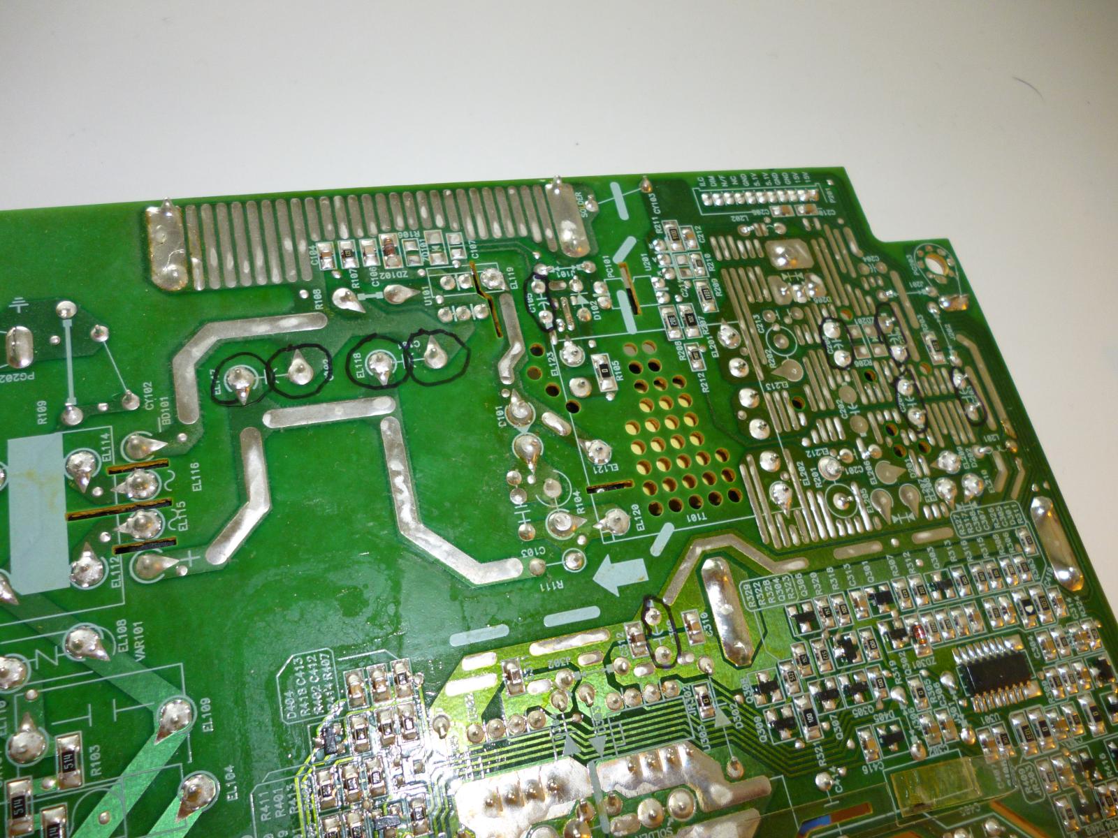
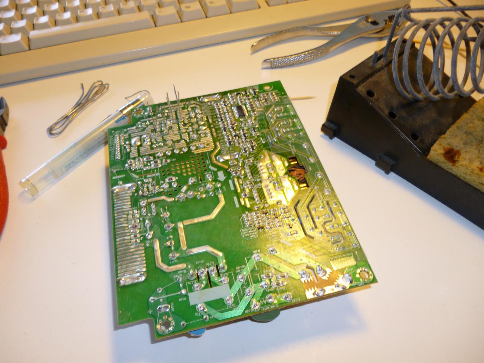
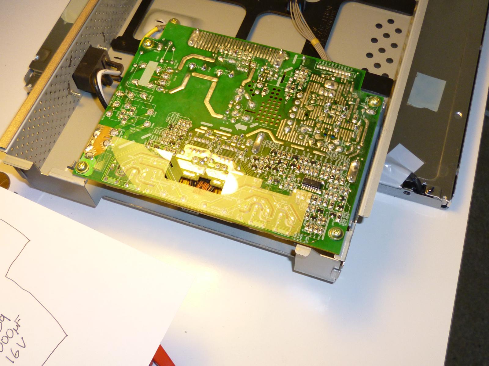
Solder side of the board with all the pads marked that need desoldering.
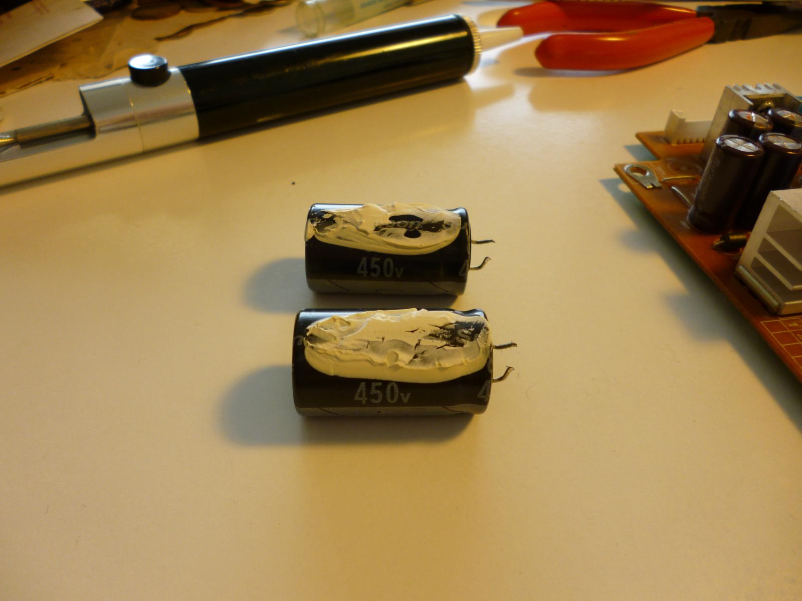
Our friends at the Lucky Goldstar company have cunningly arranged matters so that we can tell C101 and C102 are rated at 450V (yow!) but the even more important capacitance value is covered by glue.
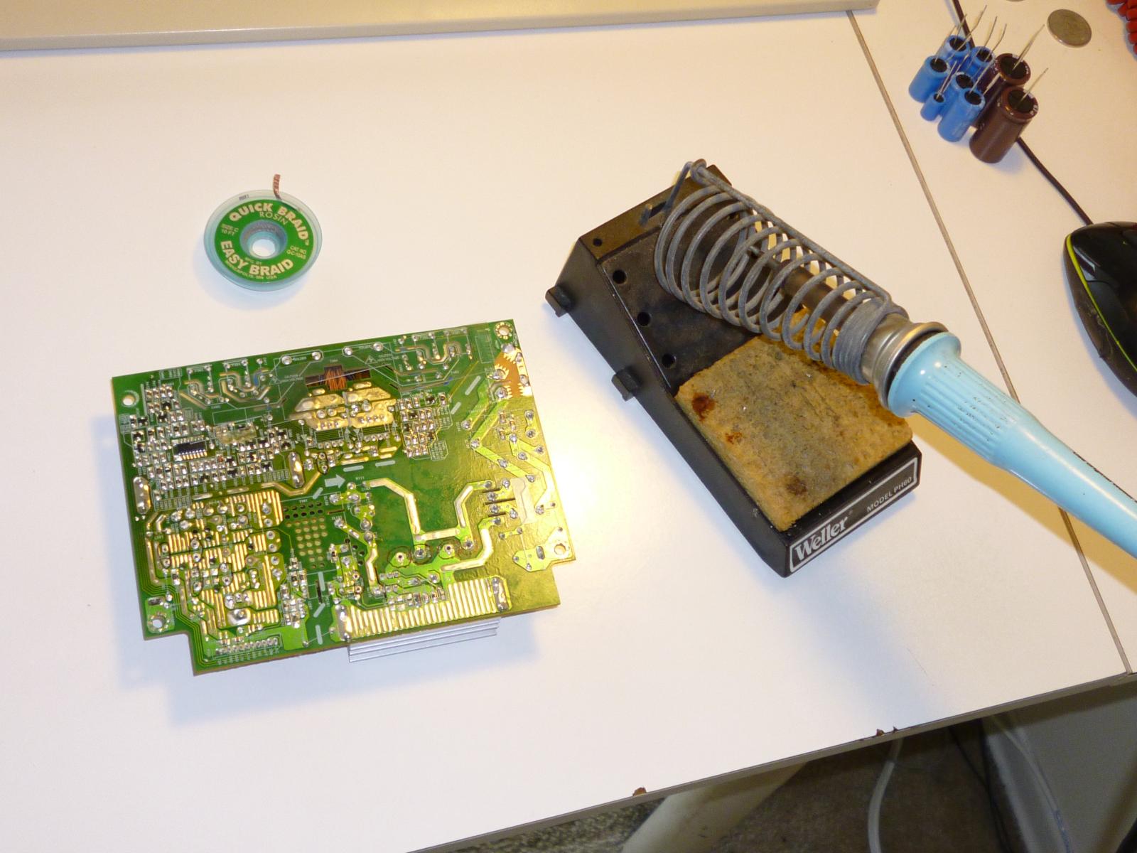
Note the tool near the top of the picture: it's a desoldering pump. I would have preferred to use desoldering braid, but couldn't find it and had to use the pump. The idea is you heat up the solder joint until it's melted, apply the pump to the joint, and press the button. It slurps up the liquid solder, to be spit into a Kleenex later. The problem is that it doesn't really work very well and requires at least three hands to use. Braid does a cleaner job. I'll have to include some in my order for the replacement capacitors.
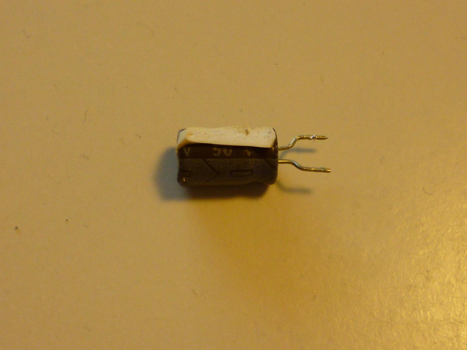
They did it again with C105 - it's a 50V unit, and (especially with that voltage rating) given its size it can't have a very high capacitance, but the actual value? Who knows?
Here's the cluster of four 1000uF caps. These were easy.
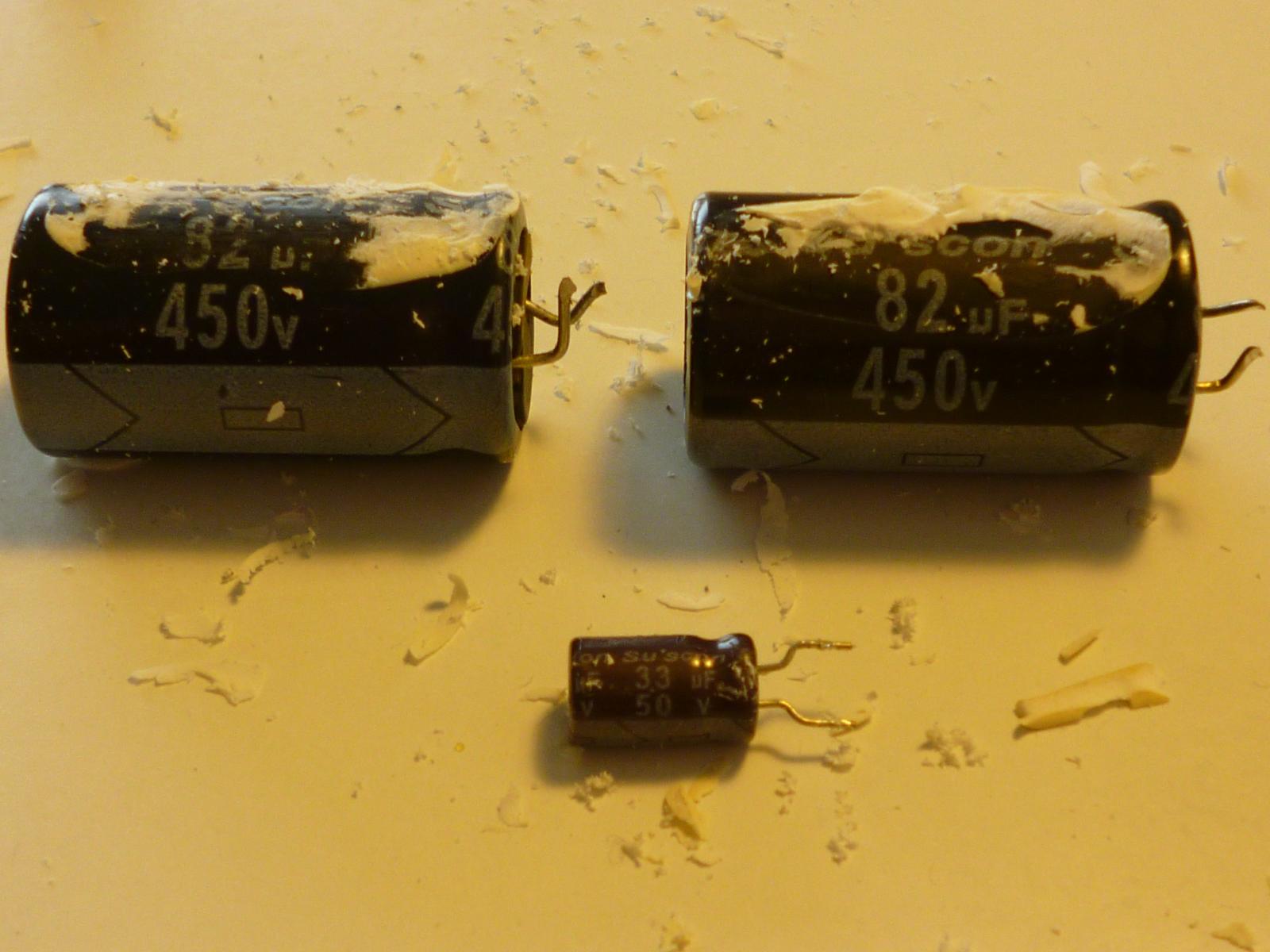
Scratch and win! I did one of the big ones first because there were two, presumably identical, and I figured that way if I destroyed it I'd still have a second chance. That proved to be good thinking, because on my first attempt I did scratch too hard and partially obliterate the marking. The other two went better. It turns out that C101 and C102 are 450V 82uF, and C105 is 50V 33uF. There is a little dot between the two digits of "33" but I'm *pretty* sure that is just a bit of unscratched glue and it's not really meant to say "3.3". If I'm wrong, I guess I'll find out.
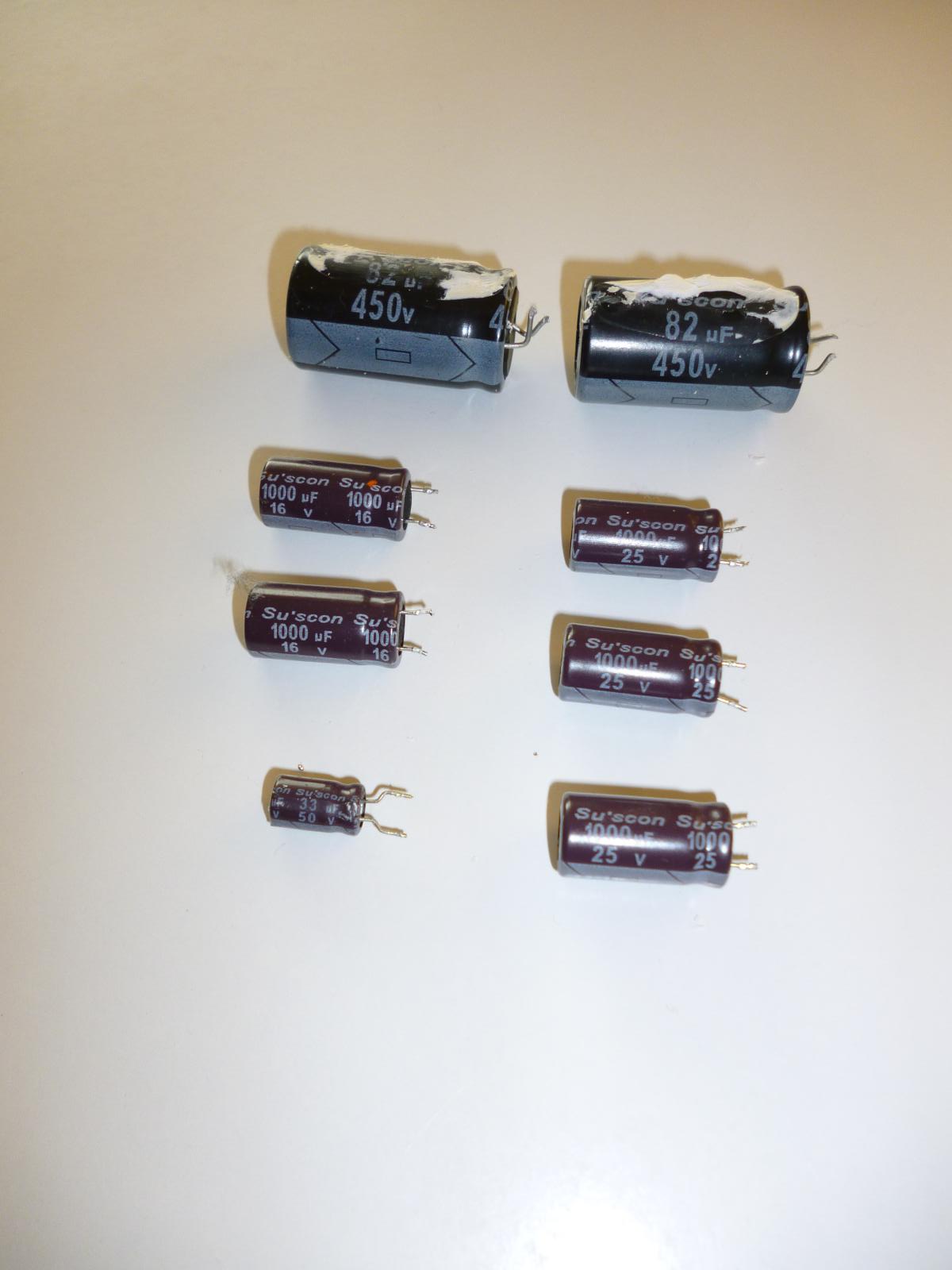
Here's the complete set of eight removed capacitors. Now I just need to replace these with eight more of the same electrical characteristics, reasonably similar physical size, and if possible, higher quality.
Board with the capacitors removed, component side. Note the big blobs of glue in some of the spaces where they were.
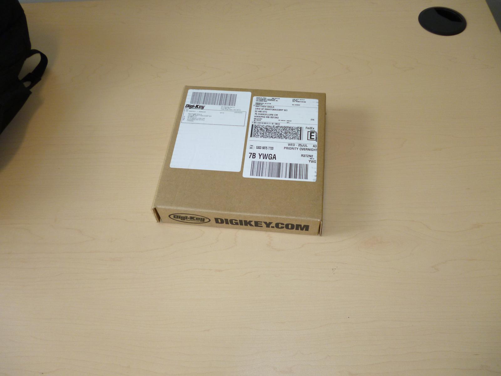
I placed the order for the replacement parts late Monday night, and they were delivered to my workplace midday Wednesday. $32.38, which is highway robbery, of course, but what are you going to do? Digi-Key has the big advantages of speed and reliability. About a third of that price tag is shipping and taxes. About $9 (note that these numbers overlap) can be attributed to the spool of desoldering braid, only a small amount of which was used for this particular job, so the real price tag might be more like $23. It turns out that Digi-Key ships to all destinations in central Canada from a warehouse right here in Winnipeg, so Fed Ex got eight bucks and 24 hours to move this small parcel all of about 20km.
Contents of the box, less a large wad of packing material, five pages of invoices and packing lists, and a small note saying basically "Check the wad of packing material carefully before you throw it out to make sure you don't accidentally discard any of the small, valuable items you bought, dumbass!"
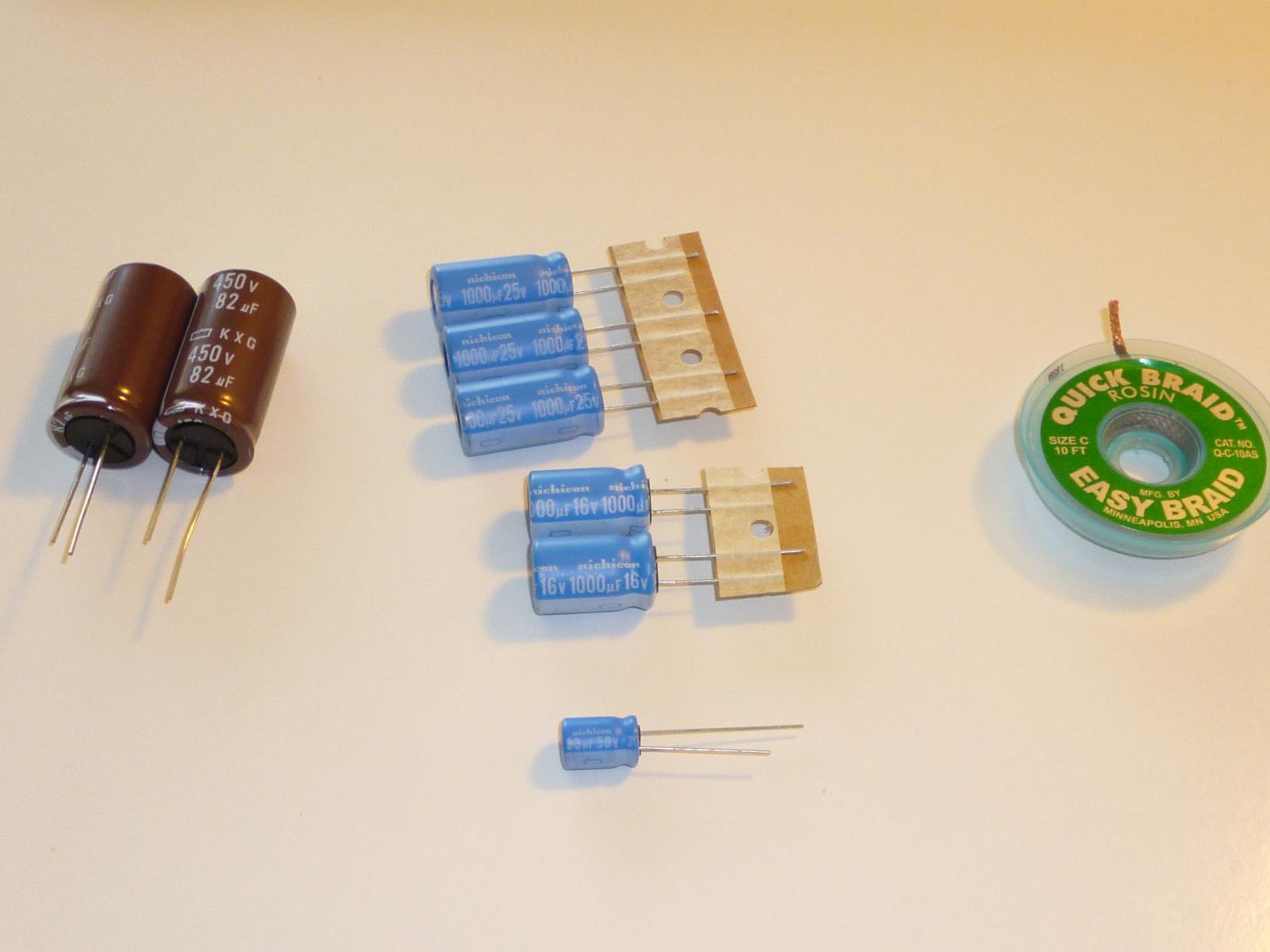
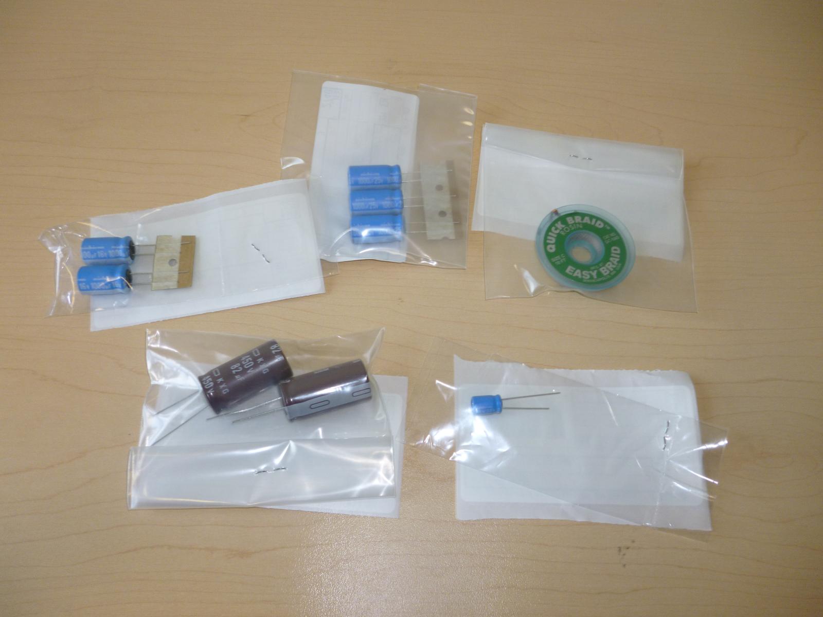
Close-up of the new parts. The brownish high-voltage capacitors are made by "United Chemi-con"; the others are from "Nichicon." According to the customs paperwork, all are Japanese except for the 50V 33uF unit (the smallest one, at the bottom), which is from Malaysia. Why is this one product from an apparently Japanese company, a Malaysian product as far as US Customs is concerned? The world wonders.
I got the highest lifetime-at-high-temperature rated components I could, because that's the issue for services inside a monitor. For the high-voltage capacitors the selection was limited, so I ended up with "10000 Hrs @ 105°C", probably the same as the ones I removed (which certainly were labelled as 105°C, hours not marked). For all the blue ones, the best available lifetime-at-temperature rating seemed to be on capacitors intended for "automotive" service: 10000 Hrs 125°C (the ones being replaced were rated for 105°C).
"Con" in both company names is probably short for コンデンサー ("kondensaa"), which is the Japanese term for "capacitor," derived from the now-obsolete English term "condensor."
I already removed the old capacitors Monday night, using the solder pump, but as I mentioned I don't really like the solder pump; and I wanted to really remove as much of the old solder as I could, partly because it's quite possibly some kind of exotic lead-free alloy that might not mix well with the traditional lead solder I'm going to use for the replacement. So here I'm getting ready to give it another going-over with the new solder braid.
New components in place, waiting for the glue to dry, with the board precariously balanced on the vise in such a way as to not strain any of the leads poking out the bottom. Our friends at the Lucky Goldstar company used some sort of hot-melt glue for the high-voltage capacitors in the original assembly (photo earlier; blobs of it still visible on, for instance, the coil at centre left) and left most of the others unglued, held in place only by gravity. But they were probably using a wave soldering machine (which keeps the board component side up and solders it from below), whereas I'm going to be hand-soldering with the board component side down; gravity will not be good enough. And I didn't have a hot-melt gun, so I ended up using large blobs of Elmer's Rubber Cement. That's far from ideal. but it'll dry soft, it won't emit acid as it cures (like the silicone caulk I briefly considered), it's good for high voltages, and I had a jar handy.
The replacement 1000uF capacitors are a little bigger in diameter than the originals. In the cluster of four at lower right you can see how they don't really fit together very nicely because the original ones were packed in tightly already. Fortunately, it isn't really tight enough to be a problem; there's enough slack in the leads to let them reach the right holes, and this part of the circuit is low-voltage. It just looks less than elegant.
Ready for the actual soldering. They're not all easy to see, but note the sticking-up leads of the replacement components.
I think I did a pretty good job for a software guy. It's not easy to distinguish my solder joints from the machine's.
Last look at the component side of the power supply board before it'll be flipped over and screwed in.
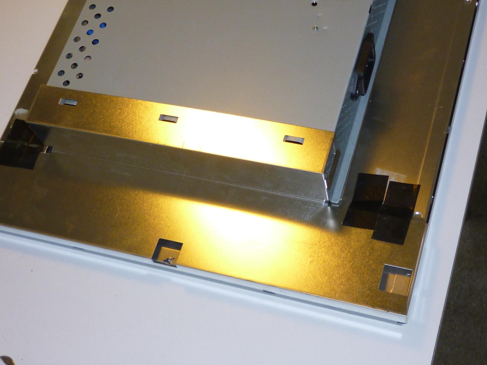
Board in place. I carefully arranged the light for this shot to make the clear plastic arc shield visible; it is now glued in place (with more rubber cement) and at a more sensible angle than before.
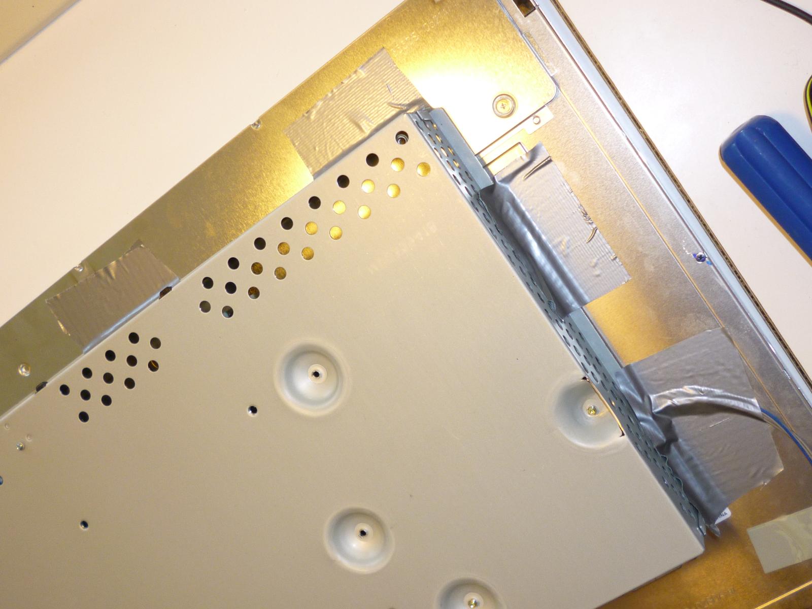
The main electronics enclosure was originally held to the display panel with just two pieces of something very closely resembling duct tape (though more cloth-y). All its mechanical support, somewhat horrifyingly, was provided by the back of the plastic enclosure. The cloth tape lost its stickiness as soon as I peeled it off, so I've replaced it with four pieces of actual duct tape. It's only attached on these two sides - I didn't want to go all the way around because of interference with other components inside the enclosure.
High-voltage shield in place. I've replaced the inscrutably blue Korean sticky tape (which had lost its stickiness almost completely over the years) with good old North American black vinyl.
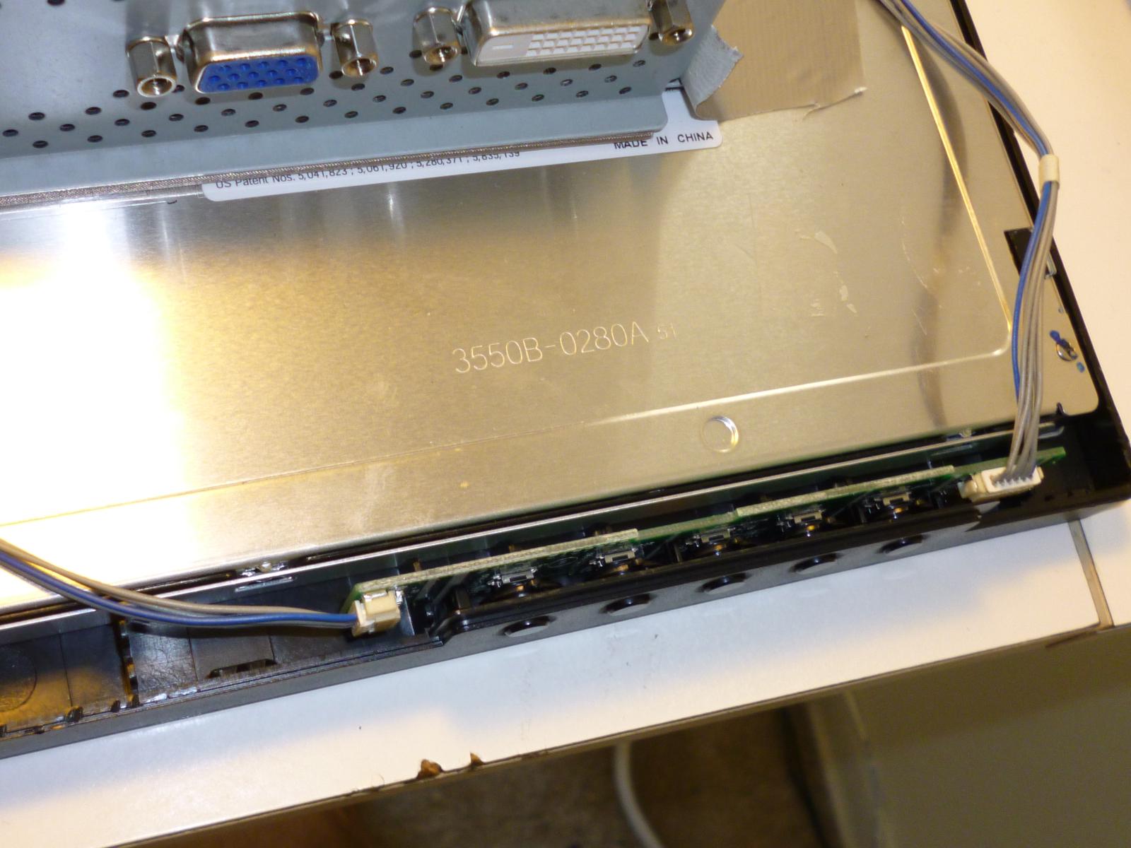
Close-up of the little circuit board that hosts the control buttons. There's another one just for the power button.
Note the "made in China" sticker. I think that refers to the LCD panel itself; the monitor has a "made in Korea" sticker on the outside, and LG is a Korean company. Most likely they buy the panel generic from China, then add other parts and do the assembly in Korea.
Bezel, plastic enclosure, and support pylon all snapped and screwed together. Except for the scars all around the edge from prying it open, which will unfortunately be permanent, we're back to where we started, physically speaking.
It works perfectly. First try. Of course it should, that was the point of the exercise; and if someone else were doubtful of my ability to fix it, I'd be insulted; but just for myself, knowing how critical the components I just replaced are and how much trouble could be caused by for instance wiring one in backward or solder-bridging some of those connections, it was quite a thrill to press the button and have it just power up without incident. No sparks or clouds of smoke or anything.
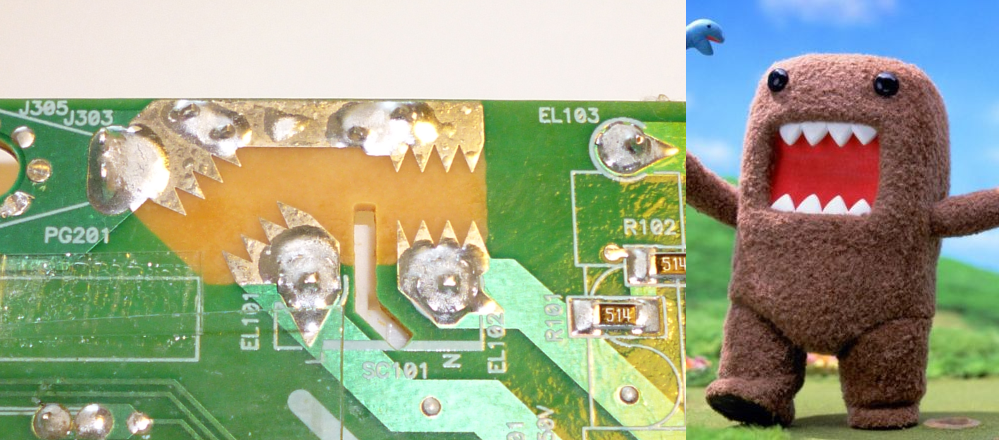
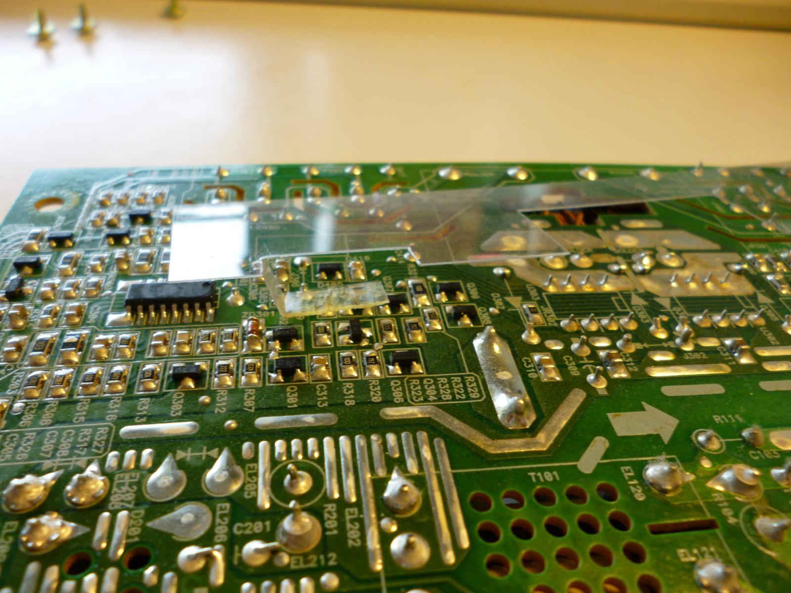
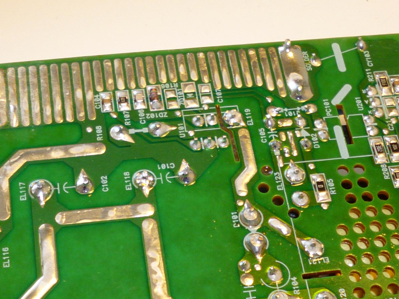
I think these are a sort of last-ditch ghetto surge suppressor. The wide traces seem to be connected to the AC power supply. In the event of a lightning strike or similar coming in through the power line, after blowing out the MOVs that protect against smaller surges, the high voltage should arc across these gaps instead of somewhere else in the circuit. The power supply would probably still be destroyed, but it might be less likely to also catch fire.
I think these gaps are about 3mm, and the dielectric strength of air is about 3kV per mm, which would work out to 9kV - but that number is assuming no sharp points, which reduce it a lot, and assuming there isn't a lot of dirt on the circuit board or humidity in the air, either of which would also reduce the spark gap voltage. All in all it's probably reasonable to guess that these gaps will arc at an unpredictable voltage somewhere between 1 and 10kV.
2 comments

Take the monitor to an org like "Komputers for kids." Either they'll fix it up and give it away or chop it up for parts and sell what's left by the kilo to a recycling plant. Or in the case of when I want to fix it myself, it's where I get used replacement parts fast and easy. They always have a box of something like capacitors for monitors. But they'd also have a box of complete circuit boards for . (They tend to have everything.) Checking with Google there is a "Computers for kids" in Winnipeg. No idea if it's the same charity franchise.
Steve - 2012-07-24 15:55
owen - 2012-07-23 17:49